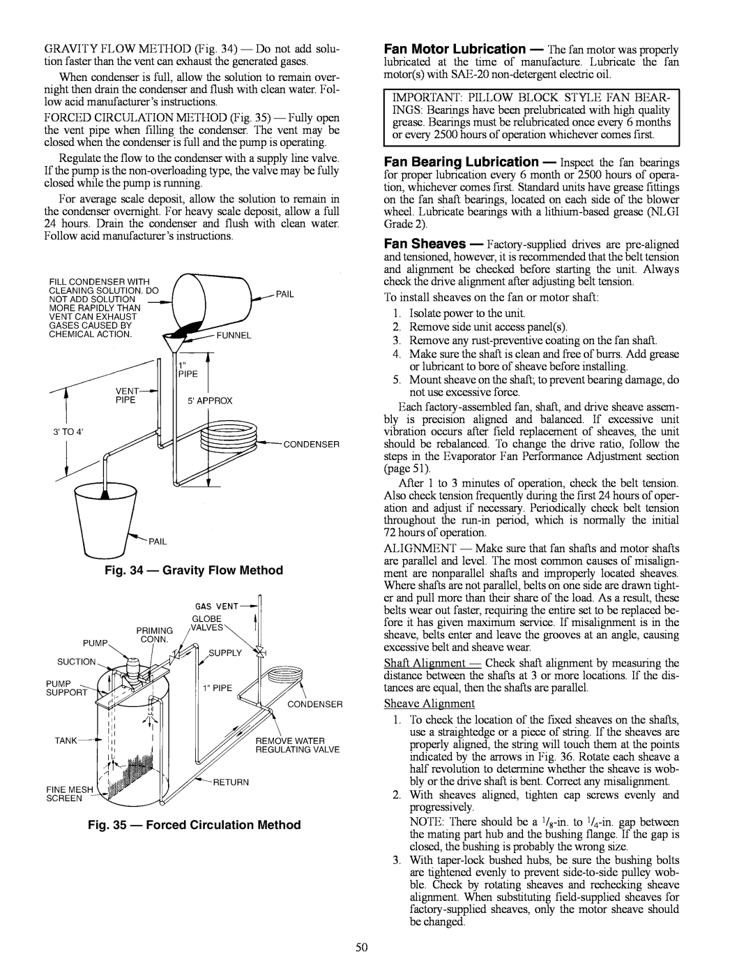
GRAVITY FLOW METHOD (Fig. 34) — Do not add solu- tion faster than the vent can exhaust the generated gases.
When condenser is full, allow the solution to remain over- night then drain the condenser and flush with clean water. Fol- low acid manufacturer’s instructions.
FORCED CIRCULATION METHOD (Fig. 35) — Fully open the vent pipe when filling the condenser. The vent may be closed when the condenser is full and the pump is operating.
Regulate the flow to the condenser with a supply line valve. If the pump is the
For average scale deposit, allow the solution to remain in the condenser overnight. For heavy scale deposit, allow a full 24 hours. Drain the condenser and flush with clean water. Follow acid manufacturer’s instructions.
a50-186tf
Fig. 34 — Gravity Flow Method
a50-187tf
Fig. 35 — Forced Circulation Method
Fan Motor Lubrication — The fan motor was properly lubricated at the time of manufacture. Lubricate the fan motor(s) with
IMPORTANT: PILLOW BLOCK STYLE FAN BEAR-
INGS: Bearings have been prelubricated with high quality grease. Bearings must be relubricated once every 6 months or every 2500 hours of operation whichever comes first.
Fan Bearing Lubrication — Inspect the fan bearings for proper lubrication every 6 month or 2500 hours of opera- tion, whichever comes first. Standard units have grease fittings on the fan shaft bearings, located on each side of the blower wheel. Lubricate bearings with a
Fan Sheaves —
To install sheaves on the fan or motor shaft:
1.Isolate power to the unit.
2.Remove side unit access panel(s).
3.Remove any
4.Make sure the shaft is clean and free of burrs. Add grease or lubricant to bore of sheave before installing.
5.Mount sheave on the shaft; to prevent bearing damage, do not use excessive force.
Each
After 1 to 3 minutes of operation, check the belt tension. Also check tension frequently during the first 24 hours of oper- ation and adjust if necessary. Periodically check belt tension throughout the
ALIGNMENT — Make sure that fan shafts and motor shafts are parallel and level. The most common causes of misalign- ment are nonparallel shafts and improperly located sheaves. Where shafts are not parallel, belts on one side are drawn tight- er and pull more than their share of the load. As a result, these belts wear out faster, requiring the entire set to be replaced be- fore it has given maximum service. If misalignment is in the sheave, belts enter and leave the grooves at an angle, causing excessive belt and sheave wear.
Shaft Alignment — Check shaft alignment by measuring the distance between the shafts at 3 or more locations. If the dis- tances are equal, then the shafts are parallel.
Sheave Alignment
1.To check the location of the fixed sheaves on the shafts, use a straightedge or a piece of string. If the sheaves are properly aligned, the string will touch them at the points indicated by the arrows in Fig. 36. Rotate each sheave a half revolution to determine whether the sheave is wob- bly or the drive shaft is bent. Correct any misalignment.
2.With sheaves aligned, tighten cap screws evenly and progressively.
NOTE: There should be a
3.With
50