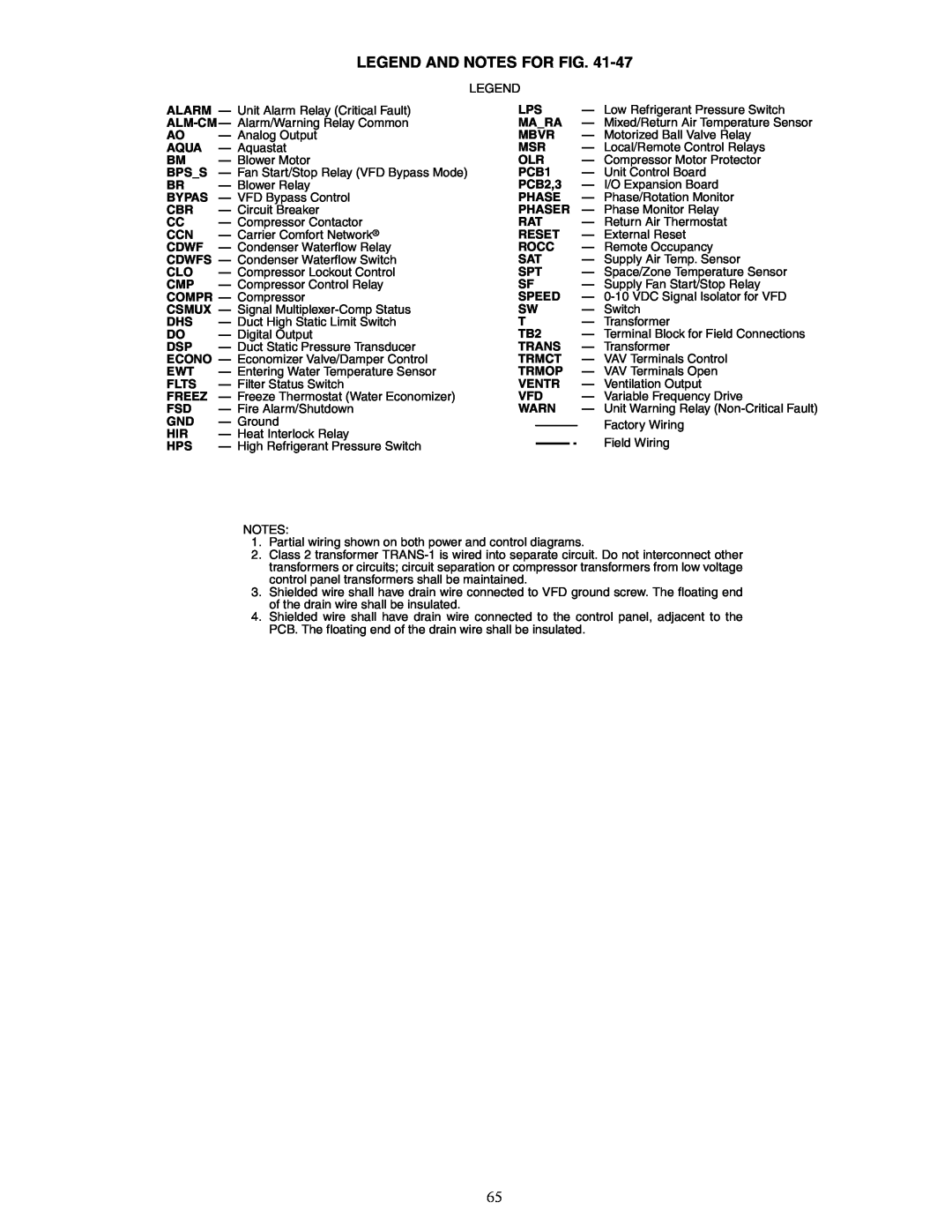
LEGEND AND NOTES FOR FIG. 41-47
LEGEND
ALARM — Unit Alarm Relay (Critical Fault)
AO | — Analog Output |
AQUA | — Aquastat |
BM | — Blower Motor |
BPS_S | — Fan Start/Stop Relay (VFD Bypass Mode) |
BR | — Blower Relay |
BYPAS | — VFD Bypass Control |
CBR | — Circuit Breaker |
CC— Compressor Contactor
CCN | — Carrier Comfort Network® |
CDWF | — Condenser Waterflow Relay |
CDWFS — Condenser Waterflow Switch | |
CLO | — Compressor Lockout Control |
CMP | — Compressor Control Relay |
COMPR — Compressor
CSMUX — Signal
DHS | — | Duct High Static Limit Switch |
DO | — | Digital Output |
DSP | — | Duct Static Pressure Transducer |
ECONO — | Economizer Valve/Damper Control | |
EWT | — | Entering Water Temperature Sensor |
FLTS | — | Filter Status Switch |
FREEZ | — | Freeze Thermostat (Water Economizer) |
FSD | — | Fire Alarm/Shutdown |
GND | — | Ground |
HIR | — | Heat Interlock Relay |
HPS | — | High Refrigerant Pressure Switch |
LPS | — Low Refrigerant Pressure Switch |
MA_RA | — Mixed/Return Air Temperature Sensor |
MBVR | — Motorized Ball Valve Relay |
MSR | — Local/Remote Control Relays |
OLR | — Compressor Motor Protector |
PCB1 | — Unit Control Board |
PCB2,3 | — I/O Expansion Board |
PHASE | — Phase/Rotation Monitor |
PHASER — Phase Monitor Relay | |
RAT | — Return Air Thermostat |
RESET | — External Reset |
ROCC | — Remote Occupancy |
SAT | — Supply Air Temp. Sensor |
SPT | — Space/Zone Temperature Sensor |
SF | — Supply Fan Start/Stop Relay |
SPEED | — |
SW | — Switch |
T— Transformer
TB2 | — Terminal Block for Field Connections |
TRANS | — Transformer |
TRMCT | — VAV Terminals Control |
TRMOP | — VAV Terminals Open |
VENTR | — Ventilation Output |
VFD | — Variable Frequency Drive |
WARN | — Unit Warning Relay |
| Factory Wiring |
| Field Wiring |
NOTES:
1.Partial wiring shown on both power and control diagrams.
2.Class 2 transformer
3.Shielded wire shall have drain wire connected to VFD ground screw. The floating end of the drain wire shall be insulated.
4.Shielded wire shall have drain wire connected to the control panel, adjacent to the PCB. The floating end of the drain wire shall be insulated.
65
