56
|
|
|
|
|
| LEGEND |
|
|
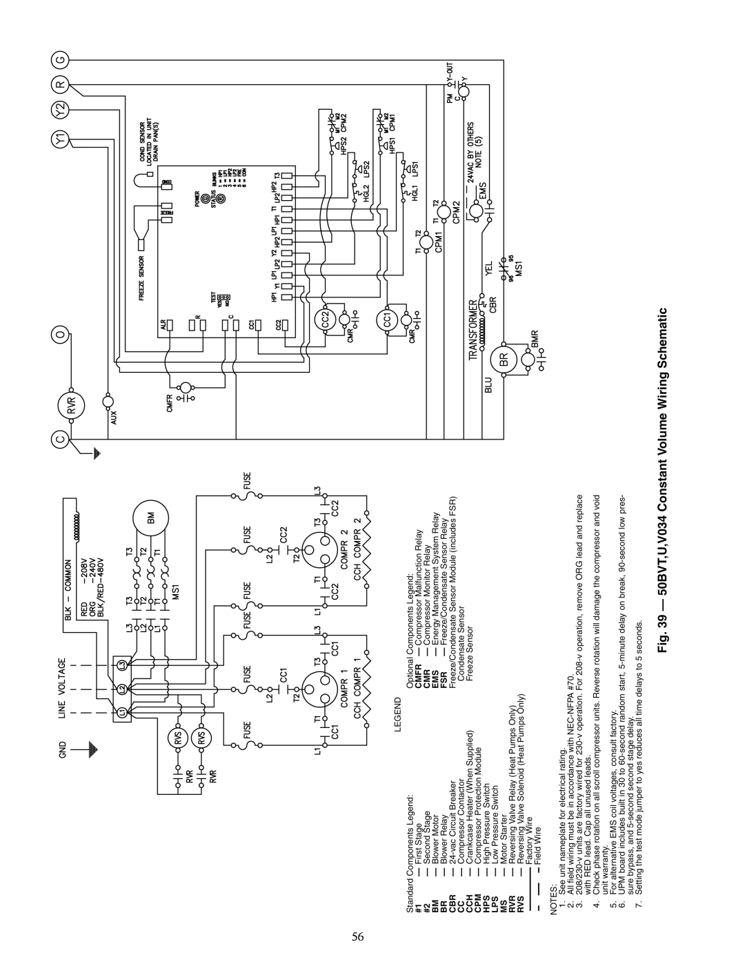
Standard Components Legend: | Optional Components Legend: | |||||||
#1 |
| — First Stage | CMFR | — Compressor Malfunction Relay | ||||
#2 |
| — Second Stage | CMR | — Compressor Monitor Relay | ||||
BM | — Blower Motor | EMS | — Energy Management System Relay | |||||
BR | — Blower Relay | FSR | — Freeze/Condensate Sensor Relay | |||||
CBR | — | Freeze/Condensate Sensor Module (includes FSR) | ||||||
CC | — Compressor Contactor | Condensate Sensor | ||||||
CCH | — Crankcase Heater (When Supplied) | Freeze Sensor | ||||||
CPM | — Compressor Protection Module |
|
| |||||
HPS | — High Pressure Switch |
|
| |||||
LPS | — Low Pressure Switch |
|
| |||||
MS | — Motor Starter |
|
| |||||
RVR | — Reversing Valve Relay (Heat Pumps Only) |
|
| |||||
RVS | — Reversing Valve Solenoid (Heat Pumps Only) |
|
| |||||
|
|
|
|
|
| Factory Wire |
|
|
|
|
|
|
|
|
|
| |
|
|
|
|
|
| Field Wire |
|
|
|
|
|
|
|
|
|
| |
NOTES:
1.See unit nameplate for electrical rating.
2.All field wiring must be in accordance with
3.
4.Check phase rotation on all scroll compressor units. Reverse rotation will damage the compressor and void unit warranty.
5.For alternative EMS coil voltages, consult factory.
6.UPM board includes built in 30 to
7.Setting the test mode jumper to yes reduces all time delays to 5 seconds.
Fig. 39 — 50BVT,U,V034 Constant Volume Wiring Schematic