Manuals
/
Carrier
/
Household Appliance
/
Air Conditioner
Carrier
50SX024-060, 50SS018-060
owner manual
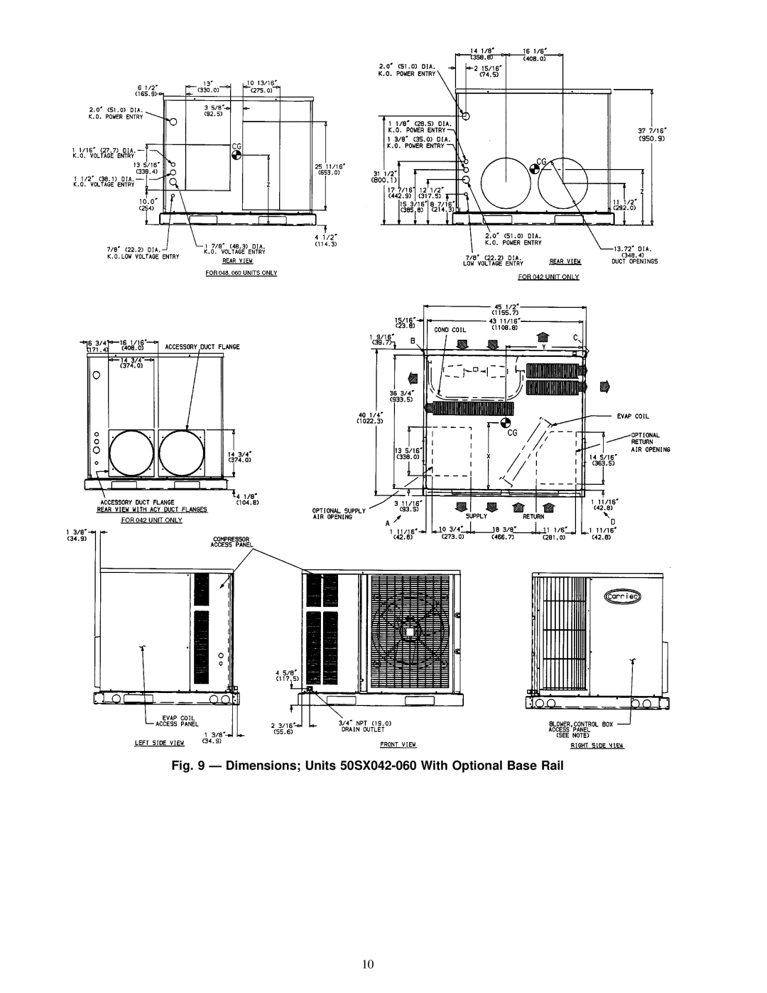
Dimensions Units 50SX042-060 With Optional Base Rail
Models:
50SS018-060
50SX024-060
1
10
48
48
Download
48 pages
10.79 Kb
7
8
9
10
11
12
13
14
Troubleshooting
Characteristics
Install
Maintenance
Evaporator Coil Access Panel
Packaged Service Training
Mode FAN Cooling Heating
Page 10
Image 10
Fig. 9 Ð Dimensions; Units
50SX042-060
With Optional Base Rail
10
Page 9
Page 11
Page 10
Image 10
Page 9
Page 11
Contents
Contents
Safety Considerations
Unit
Dimensions Units 50SS018-042 with Optional Base Rail
Dimensions Units 50SS048,060 Without Base Rail
Dimensions Units 50SS048,060 With Optional Base Rail
Dimensions Units 50SX024-036 Without Base Rail
Dimensions Units 50SX024-036 With Optional Base Rail
Dimensions Units 50SX042-060 Without Base Rail
Matl
Characteristics
Cond Ð
Unit Electrical Unit WT
Dimensions Units 50SX042-060 With Optional Base Rail
Corner WT Lb/Kg 50SX
``A
Part Number
Curb
Check Equipment
Receiving and Installation
Provide Unit Support
Suggested Rigging for Units Without Base Rail
Physical Data Ð Unit 50SS
Physical Data Ð Unit 50SX
Area Not To Be Drilled
Size
Evaporator Coil Access Panel
Indoor Blower Access Panel
Field-Fabricated Duct Cover
Provide for Condensate Disposal
Filler Bracket and Blower Shelf
Install Electrical Connections
Condensate Trap
Ð Electrical Data Ð 50SS Units
Ð Electrical Data Ð 50SX Units
Typical Duct Panel Knockouts
ICM
CTD
IFO
PRE-START-UP
Tran
Start-Up Cooling Section and Make Adjustments
START-UP
Temp F Evap AIR Ð CFM
Ð Superheat Charging Table, 50SS018
Ð Superheat Charging Table, 50SS024
AIR ENT
Ð Superheat Charging Table, 50SS042
Ð Superheat Charging Table, 50SS030
Ð Superheat Charging Table, 50SS036
1000
1600
Ð Superheat Charging Table, 50SX030
Ð Superheat Charging Table, 50SX024
1995
Ð Superheat Charging Table, 50SX048
Ð Superheat Charging Table, 50SX036
Ð Superheat Charging Table, 50SX042
1200
Superheat
Required Suction-Tube Temperature F
Ð Superheat Charging Table, 50SX060
Temp F
Terminal
Mode FAN Cooling Heating
Option Description
Sequence of Operation Ð STD NON-ICM Units
Unit Motor 460 V Horizontal Discharge
Size Speed
Unit Motor AIR 460 Volt Horizontal Discharge
048²
Unit Motor AIR 460 Volt Vertical Discharge Size
Speed Delivery
Unit 50SX FAN only Cooling
Wet Coil Pressure Drop
Accessory Electric Heater Pressure Drop in. wg
Filter Pressure Drop in. wg
Unit Top Removal
Maintenance
Air Filter
Evaporator Blower and Motor
Condenser Coil, Evaporator Coil, and Conden
Condenser Fan
Troubleshooting Cooling Chart
Symptom Cause Remedy
Troubleshooting Cooling Chart
Page
Page
Packaged Service Training
Page
Preliminary Information
Remove and Store in Job File
III. START-UP
Top
Page
Image
Contents