operation are factory-provided and mounted. The unit is factory-configured for immediate smoke detector shutdown operation; additional wiring or modifications to unit terminal board may be necessary to complete the unit and smoke detector configuration to meet project requirements.

System

The smoke detector system consists of a four-wire controller and one or two sensors. Its primary function is to shut down the rooftop unit in order to prevent smoke from circulating throughout the building. It is not to be used as a life saving device.

inspections without having to disassemble the sensor. The cover attaches to the sensor housing using four captive screws and forms an airtight chamber around the sensing electronics. Each sensor includes a harness with an RJ45 terminal for connecting to the controller. Each sensor has four LEDs (for Power, Trouble, Alarm and Dirty) and a manual test/reset button (on the left-side of the housing).

Controller


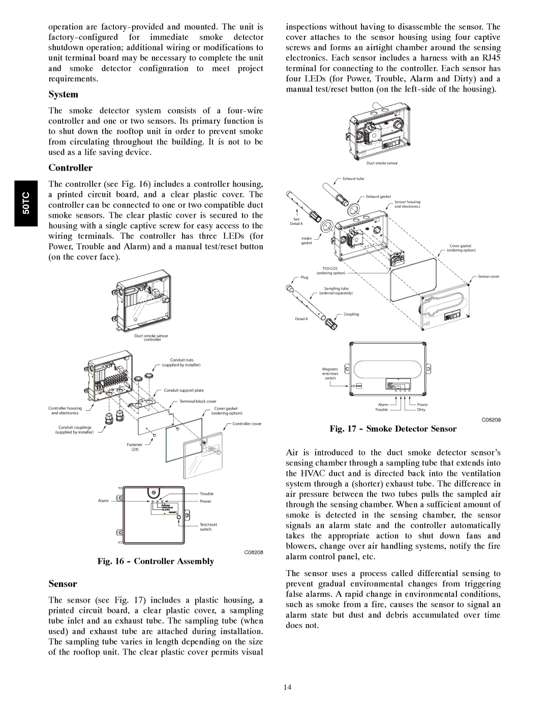
The controller (see Fig. 16) includes a controller housing,


50TC

a printed circuit board, and a clear plastic cover. The

controller can be connected to one or two compatible duct


smoke sensors. The clear plastic cover is secured to the


housing with a single captive screw for easy access to the


wiring terminals. The controller has three LEDs (for


Power, Trouble and Alarm) and a manual test/reset button


(on the cover face).

Duct smoke sensor


controller


Conduit nuts


(supplied by installer)


Conduit support plate


Terminal block cover

Controller housing

Cover gasket

and electronics

(ordering option)

Duct smoke sensor

Exhaust tube

Exhaust gasket

Sensor housing and electronics

See

Detail A

Intake gasket

TSD-CO2 (ordering option)

Plug

Sampling tube

(ordered separately)

Coupling

Detail A

Magnetic test/reset switch

Alarm

Power

Trouble

Dirty

Cover gasket

(ordering option)

Sensor cover

Controller cover

Conduit couplings

(supplied by installer)

Fastener

(2X)


Trouble

Alarm

Power


Test/reset


switch

C08208

Fig. 16 - Controller Assembly

Sensor

The sensor (see Fig. 17) includes a plastic housing, a printed circuit board, a clear plastic cover, a sampling tube inlet and an exhaust tube. The sampling tube (when used) and exhaust tube are attached during installation. The sampling tube varies in length depending on the size of the rooftop unit. The clear plastic cover permits visual

C08209

Fig. 17 - Smoke Detector Sensor

Air is introduced to the duct smoke detector sensor’s sensing chamber through a sampling tube that extends into the HVAC duct and is directed back into the ventilation system through a (shorter) exhaust tube. The difference in air pressure between the two tubes pulls the sampled air through the sensing chamber. When a sufficient amount of smoke is detected in the sensing chamber, the sensor signals an alarm state and the controller automatically takes the appropriate action to shut down fans and blowers, change over air handling systems, notify the fire alarm control panel, etc.

The sensor uses a process called differential sensing to prevent gradual environmental changes from triggering false alarms. A rapid change in environmental conditions, such as smoke from a fire, causes the sensor to signal an alarm state but dust and debris accumulated over time does not.

14

Page 14
Image 14
Carrier 50TCA04-A07 appendix System, Controller, Sensor

50TCA04-A07 specifications

The Carrier 50TCA04-A07 is a prominent model from Carrier, a leader in the heating, ventilation, and air conditioning (HVAC) industry. Designed for commercial applications, this unit exemplifies advanced technology and reliability, catering to a wide array of cooling needs.

One of the most notable features of the Carrier 50TCA04-A07 is its high efficiency. With a cooling capacity that suits various settings, it is engineered to provide excellent performance with minimal energy consumption. The unit achieves impressive Seasonal Energy Efficiency Ratio (SEER) ratings, which not only reduce operational costs but also lower the environmental impact.

The Carrier 50TCA04-A07 employs state-of-the-art inverter technology. This innovation allows the compressor to operate at varying speeds, adjusting its output according to the cooling demand. Consequently, the system can maintain optimal comfort levels while using less energy. Additionally, the inverter technology contributes to quieter operation, making it a suitable choice for environments where noise is a concern.

Durability is a hallmark of the Carrier 50TCA04-A07. Constructed with robust materials, this model is designed to withstand harsh conditions and ensure long-term reliability. The unit is equipped with corrosion-resistant components, extending its lifespan and maintaining performance quality over time.

Another significant characteristic of the Carrier 50TCA04-A07 is its advanced control system. The integrated control panel provides easy access to performance settings and monitoring capabilities. Users can effortlessly adjust temperatures and modes, ensuring a customizable climate. Furthermore, compatibility with smart building management systems enhances operational efficiency and real-time monitoring.

Regarding safety features, the Carrier 50TCA04-A07 is equipped with multiple sensors and automated responses to prevent overheating and ensure safe operation. These safety mechanisms not only protect the unit but also contribute to the overall safety of the installation environment.

In summary, the Carrier 50TCA04-A07 is a highly efficient, durable, and technologically advanced HVAC solution for commercial spaces. Its innovative features, including inverter technology, robust construction, and smart control systems, set it apart in the market, making it a reliable choice for businesses seeking to optimize their climate control needs while minimizing energy consumption and operational costs.