50TCA04-A07 specifications
The Carrier 50TCA04-A07 is a prominent model from Carrier, a leader in the heating, ventilation, and air conditioning (HVAC) industry. Designed for commercial applications, this unit exemplifies advanced technology and reliability, catering to a wide array of cooling needs.One of the most notable features of the Carrier 50TCA04-A07 is its high efficiency. With a cooling capacity that suits various settings, it is engineered to provide excellent performance with minimal energy consumption. The unit achieves impressive Seasonal Energy Efficiency Ratio (SEER) ratings, which not only reduce operational costs but also lower the environmental impact.
The Carrier 50TCA04-A07 employs state-of-the-art inverter technology. This innovation allows the compressor to operate at varying speeds, adjusting its output according to the cooling demand. Consequently, the system can maintain optimal comfort levels while using less energy. Additionally, the inverter technology contributes to quieter operation, making it a suitable choice for environments where noise is a concern.
Durability is a hallmark of the Carrier 50TCA04-A07. Constructed with robust materials, this model is designed to withstand harsh conditions and ensure long-term reliability. The unit is equipped with corrosion-resistant components, extending its lifespan and maintaining performance quality over time.
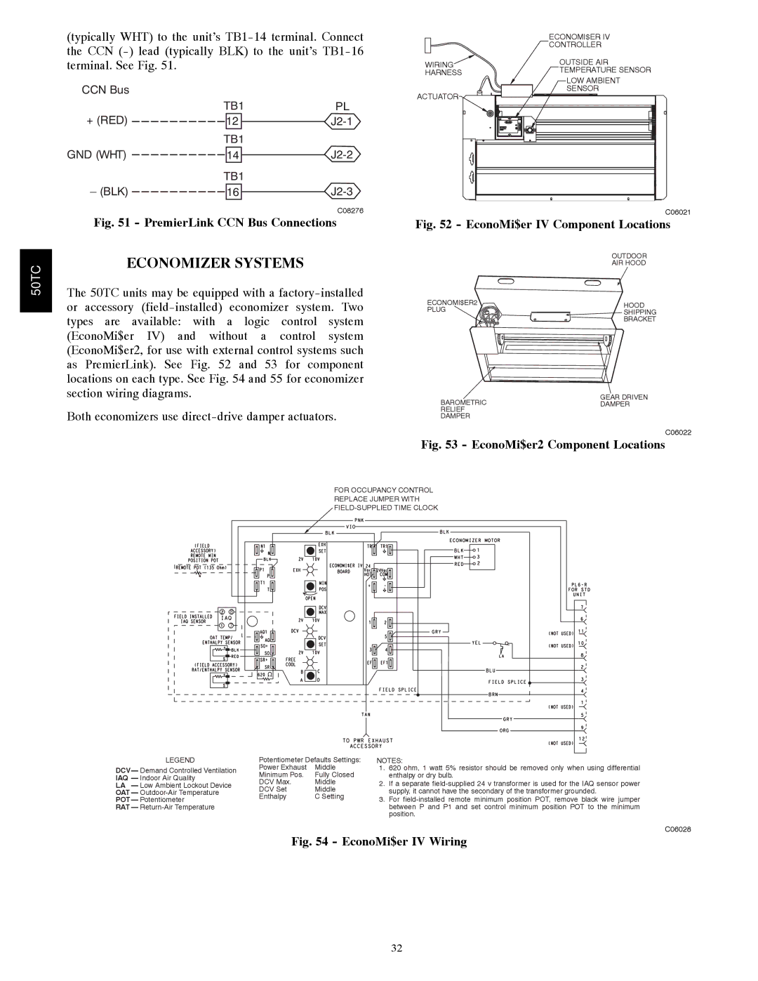
Another significant characteristic of the Carrier 50TCA04-A07 is its advanced control system. The integrated control panel provides easy access to performance settings and monitoring capabilities. Users can effortlessly adjust temperatures and modes, ensuring a customizable climate. Furthermore, compatibility with smart building management systems enhances operational efficiency and real-time monitoring.
Regarding safety features, the Carrier 50TCA04-A07 is equipped with multiple sensors and automated responses to prevent overheating and ensure safe operation. These safety mechanisms not only protect the unit but also contribute to the overall safety of the installation environment.
In summary, the Carrier 50TCA04-A07 is a highly efficient, durable, and technologically advanced HVAC solution for commercial spaces. Its innovative features, including inverter technology, robust construction, and smart control systems, set it apart in the market, making it a reliable choice for businesses seeking to optimize their climate control needs while minimizing energy consumption and operational costs.

