50TC

Single Point Boxes and Supplementary Fuses — When the unit MOCP device value exceeds 60-A,unit-mounted supplementary fuses are required for each heater circuit. These fuses are included in accessory Single Point Boxes, with power distribution and fuse blocks. The single point box will be installed directly under the unit control box, just to the left of the partition separating the indoor section (with electric heaters) from the outdoor section. The Single Point Box has a hinged access cover. See Fig 30.

CONTROL

BOX

BUSHING

SINGLE


POINT BOX


MOUNTING


SCREWS


DRIP BOOT


BRACKET


MOUNTING


SCREWS


POWER


WIRES


FOAM


BUSHING


22.2

23

1

3

HEATER

RELAYS

HEATER

MOUNTING

SCREWS

C08136

Fig. 30 - Typical Single Point Installation

On 50TC units, all fuses are 60-A. Single point boxes containing fuses for 208/230-V applications use UL Class RK5 250-V fuses (Bussman FRNR 60 or Shawmut TR 60R). Single point boxes for 460-V and 575-V applications use UL Class T 600-V fuses (Bussman JJS 60 or Shawmut A6T 60). (Note that all heaters are qualified for use with a 60-A fuse, regardless of actual heater ampacity, so only 60-A fuses are necessary.)

Unit heater applications not requiring supplemental fuses do not require a Single Point Box. Connect power supply conductors to heater conductors and field-supplied base unit power tap leads (see text below re: “Completing Heater Installation”) below the unit’s main control box using UL-approved connectors.

Safety Devices — Electric heater applications use a combination of line-break/auto-reset limit switches and a pilot-circuit/manual reset limit switch to protect the unit against over-temperature situations.

Line-break/auto-reset limit switches are mounted on the base plate of each heater module. See Fig. 31. These are accessed through the indoor access panel. Remove the switch by removing two screws into the base plate and extracting the existing switch.

Pilot-circuit/manual reset limit switch is located in the side plate of the indoor (supply) fan housing. See Fig. 28.

Completing Heater Installation

Field Power Connections — Field-supplied tap conductors must be installed between the base unit’s field power connection lugs and the splice connection between field power supply conductors and the conductors to the electric heater(s). Refer to unit wiring schematic. Use

copper wire only. Size these conductors based on the MCA (Minimum Circuit Ampacity) value marked on the 50TC unit’s info plate for the base unit less electric heater load. Use UL-approved pressure connectors (field-supplied) for these splice joints.

Line-Break

Limit Switches


23


21


13


11

ALLIED PA


MODEL

OD


NO.


ERIAL NO.


ISTED AIR


1


NDITIONING

23


UIP ACCESS

3


346N.

2-


P / N

5610-4

REV


C08330

Fig. 31 - Typical Location of Heater Limit Switches

(3-phase heater shown)

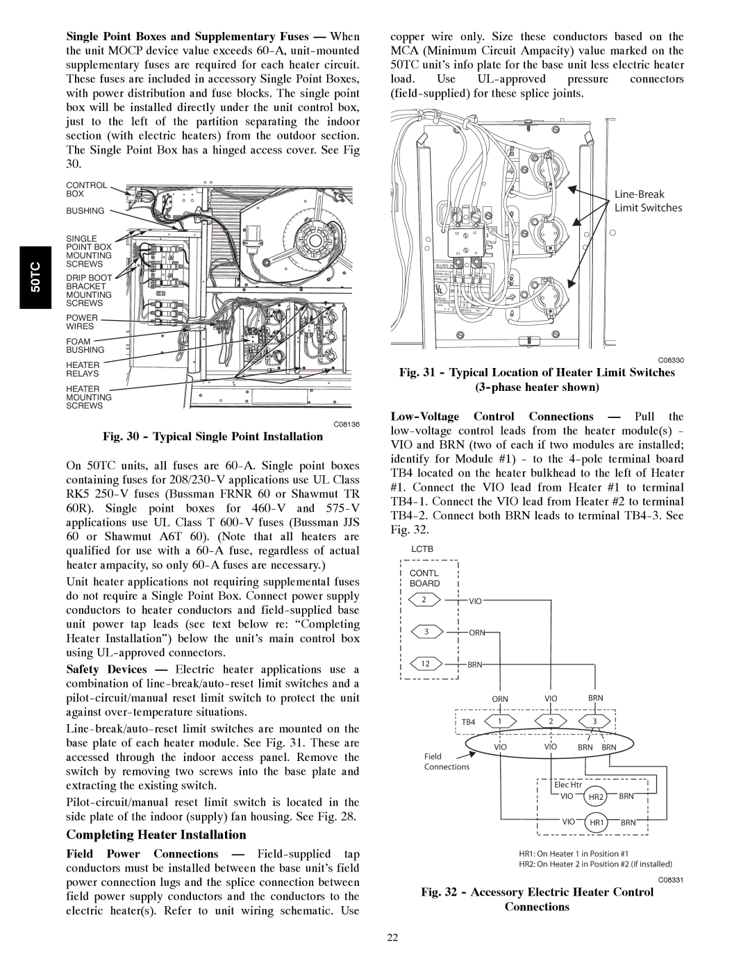
Low-Voltage Control Connections — Pull the low-voltage control leads from the heater module(s) - VIO and BRN (two of each if two modules are installed; identify for Module #1) - to the 4-pole terminal board TB4 located on the heater bulkhead to the left of Heater #1. Connect the VIO lead from Heater #1 to terminal TB4-1. Connect the VIO lead from Heater #2 to terminal TB4-2. Connect both BRN leads to terminal TB4-3. See Fig. 32.

LCTB

CONTL

BOARD

2VIO

3ORN

12 BRN


ORN

VIO

BRN

TB4

1

2

3

Field

VIO

VIO

BRN BRN


Connections


Elec Htr

VIO HR2 BRN

VIO HR1

BRN

HR1: On Heater 1 in Position #1

HR2: On Heater 2 in Position #2 (if installed)

C08331

Fig. 32 - Accessory Electric Heater Control

Connections

22

Page 22
Image 22
Carrier 50TCA04-A07 appendix Completing Heater Installation, Typical Single Point Installation

50TCA04-A07 specifications

The Carrier 50TCA04-A07 is a prominent model from Carrier, a leader in the heating, ventilation, and air conditioning (HVAC) industry. Designed for commercial applications, this unit exemplifies advanced technology and reliability, catering to a wide array of cooling needs.

One of the most notable features of the Carrier 50TCA04-A07 is its high efficiency. With a cooling capacity that suits various settings, it is engineered to provide excellent performance with minimal energy consumption. The unit achieves impressive Seasonal Energy Efficiency Ratio (SEER) ratings, which not only reduce operational costs but also lower the environmental impact.

The Carrier 50TCA04-A07 employs state-of-the-art inverter technology. This innovation allows the compressor to operate at varying speeds, adjusting its output according to the cooling demand. Consequently, the system can maintain optimal comfort levels while using less energy. Additionally, the inverter technology contributes to quieter operation, making it a suitable choice for environments where noise is a concern.

Durability is a hallmark of the Carrier 50TCA04-A07. Constructed with robust materials, this model is designed to withstand harsh conditions and ensure long-term reliability. The unit is equipped with corrosion-resistant components, extending its lifespan and maintaining performance quality over time.

Another significant characteristic of the Carrier 50TCA04-A07 is its advanced control system. The integrated control panel provides easy access to performance settings and monitoring capabilities. Users can effortlessly adjust temperatures and modes, ensuring a customizable climate. Furthermore, compatibility with smart building management systems enhances operational efficiency and real-time monitoring.

Regarding safety features, the Carrier 50TCA04-A07 is equipped with multiple sensors and automated responses to prevent overheating and ensure safe operation. These safety mechanisms not only protect the unit but also contribute to the overall safety of the installation environment.

In summary, the Carrier 50TCA04-A07 is a highly efficient, durable, and technologically advanced HVAC solution for commercial spaces. Its innovative features, including inverter technology, robust construction, and smart control systems, set it apart in the market, making it a reliable choice for businesses seeking to optimize their climate control needs while minimizing energy consumption and operational costs.