CO2 SENSOR MAX RANGE SETTING


6000


(ppm)

5000


CONFIGURATION

4000


800 ppm


3000


900 ppm


1000 ppm


2000


1100 ppm


RANGE

1000


0


2

3

4

5

6

7

8


DAMPER VOLTAGE FOR MAX VENTILATION RATE

C06039

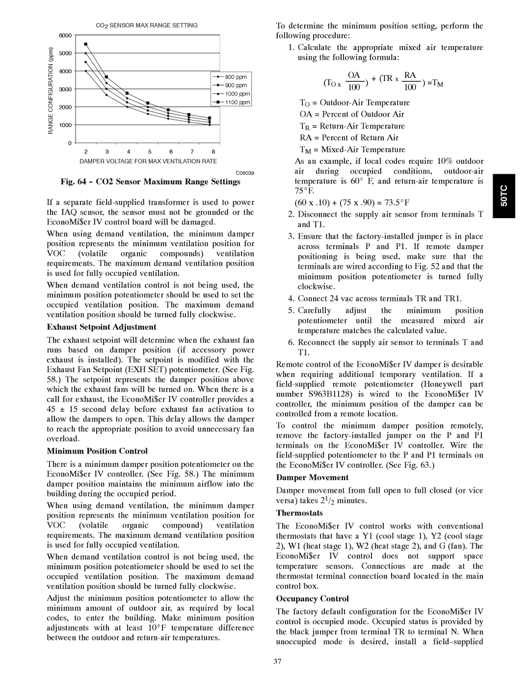
Fig. 64 - CO2 Sensor Maximum Range Settings

If a separate field-supplied transformer is used to power the IAQ sensor, the sensor must not be grounded or the EconoMi$er IV control board will be damaged.

When using demand ventilation, the minimum damper position represents the minimum ventilation position for VOC (volatile organic compounds) ventilation requirements. The maximum demand ventilation position is used for fully occupied ventilation.

When demand ventilation control is not being used, the minimum position potentiometer should be used to set the occupied ventilation position. The maximum demand ventilation position should be turned fully clockwise.

Exhaust Setpoint Adjustment

The exhaust setpoint will determine when the exhaust fan runs based on damper position (if accessory power exhaust is installed). The setpoint is modified with the Exhaust Fan Setpoint (EXH SET) potentiometer. (See Fig. 58.) The setpoint represents the damper position above which the exhaust fans will be turned on. When there is a call for exhaust, the EconoMi$er IV controller provides a 45 ± 15 second delay before exhaust fan activation to allow the dampers to open. This delay allows the damper to reach the appropriate position to avoid unnecessary fan overload.

Minimum Position Control

There is a minimum damper position potentiometer on the EconoMi$er IV controller. (See Fig. 58.) The minimum damper position maintains the minimum airflow into the building during the occupied period.

When using demand ventilation, the minimum damper position represents the minimum ventilation position for VOC (volatile organic compound) ventilation requirements. The maximum demand ventilation position is used for fully occupied ventilation.

When demand ventilation control is not being used, the minimum position potentiometer should be used to set the occupied ventilation position. The maximum demand ventilation position should be turned fully clockwise.

Adjust the minimum position potentiometer to allow the minimum amount of outdoor air, as required by local codes, to enter the building. Make minimum position adjustments with at least 10_F temperature difference between the outdoor and return-air temperatures.

To determine the minimum position setting, perform the following procedure:

1.Calculate the appropriate mixed air temperature using the following formula:

(TO x 100OA ) + (TR x 100RA ) =TM

TO = Outdoor-Air Temperature

OA = Percent of Outdoor Air

TR = Return-Air Temperature

RA = Percent of Return Air

TM = Mixed-Air Temperature

As an example, if local codes require 10% outdoor air during occupied conditions, outdoor-air temperature is 60_ F, and return-air temperature is 75_F.

(60 x .10) + (75 x .90) = 73.5_F

2.Disconnect the supply air sensor from terminals T and T1.

3.Ensure that the factory-installed jumper is in place across terminals P and P1. If remote damper positioning is being used, make sure that the terminals are wired according to Fig. 52 and that the minimum position potentiometer is turned fully clockwise.

4.Connect 24 vac across terminals TR and TR1.

5.Carefully adjust the minimum position potentiometer until the measured mixed air temperature matches the calculated value.

6.Reconnect the supply air sensor to terminals T and T1.

Remote control of the EconoMi$er IV damper is desirable when requiring additional temporary ventilation. If a field-supplied remote potentiometer (Honeywell part number S963B1128) is wired to the EconoMi$er IV controller, the minimum position of the damper can be controlled from a remote location.

To control the minimum damper position remotely, remove the factory-installed jumper on the P and P1 terminals on the EconoMi$er IV controller. Wire the field-supplied potentiometer to the P and P1 terminals on the EconoMi$er IV controller. (See Fig. 63.)

Damper Movement

Damper movement from full open to full closed (or vice versa) takes 21/2 minutes.

Thermostats

The EconoMi$er IV control works with conventional thermostats that have a Y1 (cool stage 1), Y2 (cool stage 2), W1 (heat stage 1), W2 (heat stage 2), and G (fan). The EconoMi$er IV control does not support space temperature sensors. Connections are made at the thermostat terminal connection board located in the main control box.

Occupancy Control

The factory default configuration for the EconoMi$er IV control is occupied mode. Occupied status is provided by the black jumper from terminal TR to terminal N. When unoccupied mode is desired, install a field-supplied

50TC

37

Page 37
Image 37
Carrier 50TCA04-A07 Exhaust Setpoint Adjustment, Minimum Position Control, Damper Movement, Thermostats, Occupancy Control

50TCA04-A07 specifications

The Carrier 50TCA04-A07 is a prominent model from Carrier, a leader in the heating, ventilation, and air conditioning (HVAC) industry. Designed for commercial applications, this unit exemplifies advanced technology and reliability, catering to a wide array of cooling needs.

One of the most notable features of the Carrier 50TCA04-A07 is its high efficiency. With a cooling capacity that suits various settings, it is engineered to provide excellent performance with minimal energy consumption. The unit achieves impressive Seasonal Energy Efficiency Ratio (SEER) ratings, which not only reduce operational costs but also lower the environmental impact.

The Carrier 50TCA04-A07 employs state-of-the-art inverter technology. This innovation allows the compressor to operate at varying speeds, adjusting its output according to the cooling demand. Consequently, the system can maintain optimal comfort levels while using less energy. Additionally, the inverter technology contributes to quieter operation, making it a suitable choice for environments where noise is a concern.

Durability is a hallmark of the Carrier 50TCA04-A07. Constructed with robust materials, this model is designed to withstand harsh conditions and ensure long-term reliability. The unit is equipped with corrosion-resistant components, extending its lifespan and maintaining performance quality over time.

Another significant characteristic of the Carrier 50TCA04-A07 is its advanced control system. The integrated control panel provides easy access to performance settings and monitoring capabilities. Users can effortlessly adjust temperatures and modes, ensuring a customizable climate. Furthermore, compatibility with smart building management systems enhances operational efficiency and real-time monitoring.

Regarding safety features, the Carrier 50TCA04-A07 is equipped with multiple sensors and automated responses to prevent overheating and ensure safe operation. These safety mechanisms not only protect the unit but also contribute to the overall safety of the installation environment.

In summary, the Carrier 50TCA04-A07 is a highly efficient, durable, and technologically advanced HVAC solution for commercial spaces. Its innovative features, including inverter technology, robust construction, and smart control systems, set it apart in the market, making it a reliable choice for businesses seeking to optimize their climate control needs while minimizing energy consumption and operational costs.