CONTENTS
Installation, Start-Upand Service Instructions
Compressor Suction and Discharge
CONTENTS cont
SAFETY CONSIDERATIONS
GENERAL
INSTALLATION
Install Outdoor Hoods
Copy continues on page
Table 1 Ð Physical Data
Table1 Ð Physical Data cont
Table 3 Ð Compressor Oil Charge
Table 2 Ð Optional Power Exhaust Specications
Fig. 1 Ð Roof Curb Dimensions, 48/50MP62L and 70M
Fig. 2 Ð Roof Curb Dimensions, 48/50MP82N-10R
Fig. 3 Ð Base Unit Dimensions, 48MP62L, 70M
Fig. 4 Ð Base Unit Dimensions, 48MP82N-10R
Fig. 5 Ð Base Unit Dimensions, 50MP62L and 70M
Fig. 6 Ð Base Unit Dimensions, 50MP82N-10R
Fig. 7 Ð Rigging Label
Fig. 9 Ð Condensate Drain Piping Details
Fig. 11 Ð Outdoor Air Hoods Installed
Field Electrical Connections
Make Electrical Connections
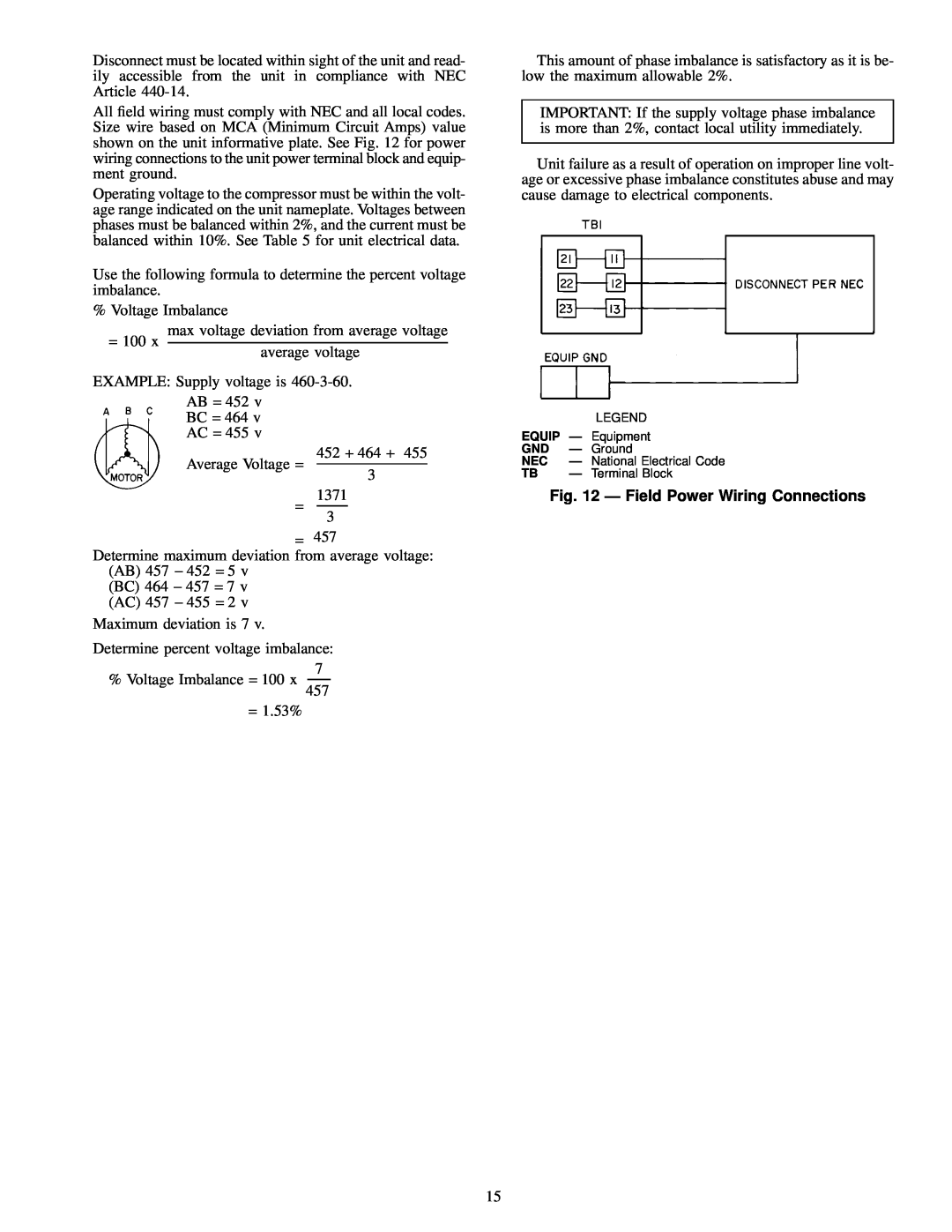
Fig. 12 Ð Field Power Wiring Connections
Table 5 Ð Electrical Data
Device Non-ShieldedCable
Table 6 Ð Recommended Sensor and
Fig. 13 Ð Space Temperature Sensor Wiring
Fig. 14 Ð Space Temperature Sensor Averaging
Fig. 19 Ð Fire/Smoke Control
Fig. 18 Ð Accessory Humidity Control
Fig. 15 Ð Heat Interlock Relay
Fig. 16 Ð Differential Enthalpy Sensor
Fig. 22 Ð Timed Discrete Output
Fig. 26 Ð Remote Supply Air Temperature
Reset/Space Temperature Offset
Fig. 21 Ð Outdoor Air¯ow Control
TRANSDUCER ACCESSORY
Fig. 27 Ð Transducer/Thermistor
Fig. 28 Ð CCN Building Supervisor
Table 7 Ð CCN Connection Approved Shielded Cables
Fig. 29 Ð Optional VFD Ð Wiring Connections
The following color code is recommended
Fig. 32 Ð Auxiliary Control Box
Fig. 31 Ð Auxiliary Control Box Location
50MP70M Unit Shown
Fig. 33 Ð Air Pressure Tubing Locations
Fig. 35 Ð Flue and Inlet Hood Locations
Installing Flue/Inlet Hoods 48MP Units Only
Fig. 36 Ð Inlet Hood Assembly Fig. 37 Ð Flue Hood
Fig. 34 Ð Gas Piping Details
Fig. 40 Ð Outer View, Compressor Mounting
Fig. 39 Ð Fan isolator Adjustment
Check Compressor Mounting
Fig. 38 Ð Flue De¯ector Baffle Assembled
System Check
Rail Assembly Ð 48/50MP70M-10RUnits
Rail Assembly Ð 48/50MP70M-10RUnits
PRE-START-UP
Fig. 44 Ð Operating Oil Levels Sight Glass
Evaporator-FanBelts, Pulleys, and Sheaves Ð
AIRFLOW
AIRFLOW
Table 13 Ð Fan Performance Air Foil Ð 48/50MP62L
Table 15 Ð Fan Performance Air Foil Ð 48/50MP82N
Table 14 Ð Fan Performance Air Foil Ð 48/50MP70M
Table 17 Ð Fan Performance Air Foil Ð 48/50MP10R
Table 16 Ð Fan Performance Air Foil Ð 48/50MP90P
Table 18 Ð Component Pressure Drop in. wg
Table 20 Ð Maximum Allowable Power Exhaust
Table 22 Ð Filter Switch Dirty Set Point
Controls Conguration and Quick Test
Enthalpy Sensor HH57AC077
Fig. 46 Ð Psychrometric Chart for
Fig. 47 Ð Wiring Connections for Solid-State
Enthalpy Control
Table 24 Ð Set Point Ranges and Defaults
Table 25 Ð Basic Conguration Data
START-UP Initial Check
General
Table 26 Ð IGC Control Board LED Alarms
Control Loop Checkout
Compressors
CONTROL SYSTEM
Components
Table 29 Ð Index of Lead/Lag Circuits and
KEYPAD AND DISPLAY MODULE HSIO
FUNCTIONS
SERVICE
Table 30 Ð Variable Frequency Drive VFD Display
Fig. 49 Ð VFD Digital Operator
Fig. 50 Ð Door Latch
Fig. 51 Ð Access Locations 48MP70M Unit Shown
Fig. 53 Ð Removing Heat Exchanger Ceramic
Lubrication
Refrigerant Circuit
Fig. 52 Ð Burner Section Detail
Fig. 55 Ð Charging Chart Ð Unit 48/50MP62L
Fig. 56 Ð Charging Chart Ð Unit 48/50MP70M
Fig. 57 Ð Chrging Chart Ð Unit 48/50MP82N
Fig. 59 Ð Charging Chart Ð Unit 48/50MP10R
Fig. 58 Ð Charging Chart Unit 48/50MP90P
Adjustments
Fig. 60 Ð 06E Compressors, Typical
Fig. 61 Ð Motor Plate Adjustment
Fig. 63 Ð Gas Valve
Gas Valve Adjustment
Protective Devices
Fig. 62 Ð Pulley Alignment
Variable Frequency Drive VFD
Installation
Processor Modules PSIO
High-VoltageRelay Modules DSIO1 and DSIO2
Compressor Replacement Ð Perform the following
TROUBLESHOOTING
Fig. 64 Ð Condenser Fan Adjustment
TROUBLESHOOTING AND DIAGNOSTICS
TROUBLESHOOTING AND DIAGNOSTICS cont
Fig. 65 Ð IGC Control Heating Ð 48MP Units Only
Page
CALL FOR FREE CATALOG
PACKAGED SERVICE TRAINING
I. PRE-START-UP
START-UPCHECKLIST
IV. START-UP
III.PRELIMINARY CHECKLIST ITEMS cont
CHANGES TO DEFAULT VALUES
TEMPERATURES
KEYBOARD
CONTROL CONFIGURATION
VALUES IN INDICATE FACTORY DEFAULTS
CL-3
DESCRIPTION
CONSTANT VOLUME CONTROL CONFIGURATION
KEYBOARD
DISPLAY