Control Wiring Ð See Fig. 13 for sensor wiring con- nections to main and auxiliary control boxes. The recom- mended types of control wiring for 48/50MP unit devices are shown in Table 6.
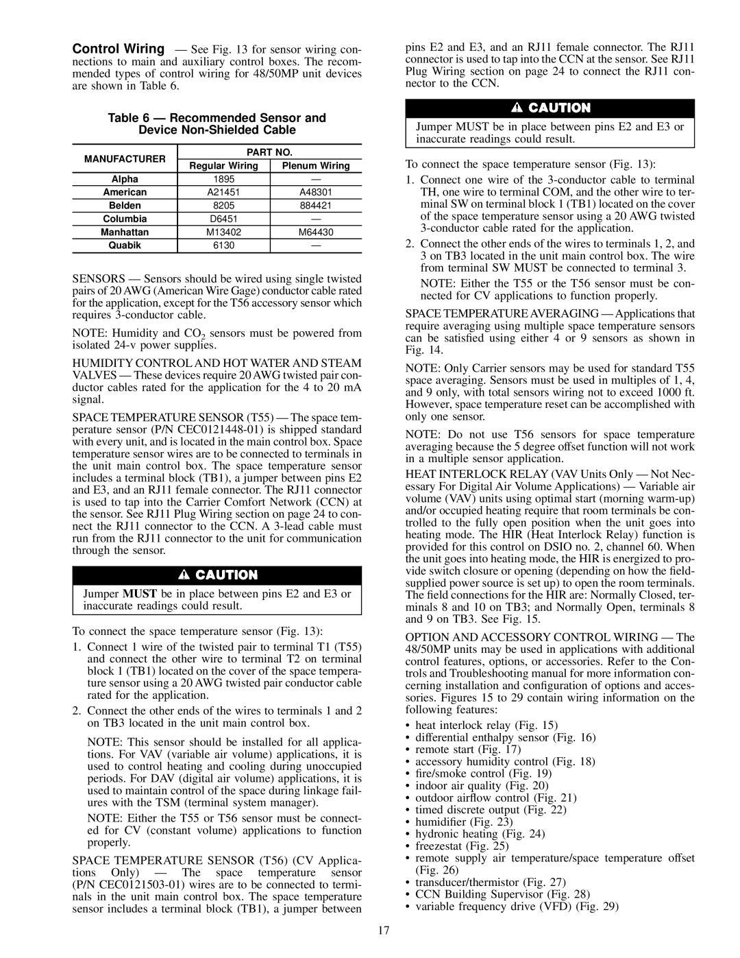
Table 6 Ð Recommended Sensor and
Device Non-Shielded Cable
| MANUFACTURER | PART NO. |
| Regular Wiring | Plenum Wiring |
| |
| Alpha | 1895 | Ð |
| American | A21451 | A48301 |
| Belden | 8205 | 884421 |
| Columbia | D6451 | Ð |
| Manhattan | M13402 | M64430 |
| Quabik | 6130 | Ð |
| | | |
SENSORS Ð Sensors should be wired using single twisted pairs of 20 AWG (American Wire Gage) conductor cable rated for the application, except for the T56 accessory sensor which requires 3-conductor cable.
NOTE: Humidity and CO2 sensors must be powered from isolated 24-v power supplies.
HUMIDITY CONTROL AND HOT WATER AND STEAM VALVES Ð These devices require 20 AWG twisted pair con- ductor cables rated for the application for the 4 to 20 mA signal.
SPACE TEMPERATURE SENSOR (T55) Ð The space tem- perature sensor (P/N CEC0121448-01) is shipped standard with every unit, and is located in the main control box. Space temperature sensor wires are to be connected to terminals in the unit main control box. The space temperature sensor includes a terminal block (TB1), a jumper between pins E2 and E3, and an RJ11 female connector. The RJ11 connector is used to tap into the Carrier Comfort Network (CCN) at the sensor. See RJ11 Plug Wiring section on page 24 to con- nect the RJ11 connector to the CCN. A 3-lead cable must run from the RJ11 connector to the unit for communication through the sensor.
Jumper MUST be in place between pins E2 and E3 or inaccurate readings could result.
To connect the space temperature sensor (Fig. 13):
1.Connect 1 wire of the twisted pair to terminal T1 (T55) and connect the other wire to terminal T2 on terminal block 1 (TB1) located on the cover of the space tempera- ture sensor using a 20 AWG twisted pair conductor cable rated for the application.
2.Connect the other ends of the wires to terminals 1 and 2 on TB3 located in the unit main control box.
NOTE: This sensor should be installed for all applica- tions. For VAV (variable air volume) applications, it is used to control heating and cooling during unoccupied periods. For DAV (digital air volume) applications, it is used to maintain control of the space during linkage fail- ures with the TSM (terminal system manager).
NOTE: Either the T55 or T56 sensor must be connect- ed for CV (constant volume) applications to function properly.
SPACE TEMPERATURE SENSOR (T56) (CV Applica- tions Only) Ð The space temperature sensor (P/N CEC0121503-01) wires are to be connected to termi- nals in the unit main control box. The space temperature sensor includes a terminal block (TB1), a jumper between
pins E2 and E3, and an RJ11 female connector. The RJ11 connector is used to tap into the CCN at the sensor. See RJ11 Plug Wiring section on page 24 to connect the RJ11 con- nector to the CCN.
Jumper MUST be in place between pins E2 and E3 or inaccurate readings could result.
To connect the space temperature sensor (Fig. 13):
1.Connect one wire of the 3-conductor cable to terminal TH, one wire to terminal COM, and the other wire to ter- minal SW on terminal block 1 (TB1) located on the cover of the space temperature sensor using a 20 AWG twisted 3-conductor cable rated for the application.
2.Connect the other ends of the wires to terminals 1, 2, and 3 on TB3 located in the unit main control box. The wire from terminal SW MUST be connected to terminal 3.
NOTE: Either the T55 or the T56 sensor must be con- nected for CV applications to function properly.
SPACE TEMPERATURE AVERAGING Ð Applications that require averaging using multiple space temperature sensors can be satis®ed using either 4 or 9 sensors as shown in Fig. 14.
NOTE: Only Carrier sensors may be used for standard T55 space averaging. Sensors must be used in multiples of 1, 4, and 9 only, with total sensors wiring not to exceed 1000 ft. However, space temperature reset can be accomplished with only one sensor.
NOTE: Do not use T56 sensors for space temperature averaging because the 5 degree offset function will not work in a multiple sensor application.
HEAT INTERLOCK RELAY (VAV Units Only Ð Not Nec- essary For Digital Air Volume Applications) Ð Variable air volume (VAV) units using optimal start (morning warm-up) and/or occupied heating require that room terminals be con- trolled to the fully open position when the unit goes into heating mode. The HIR (Heat Interlock Relay) function is provided for this control on DSIO no. 2, channel 60. When the unit goes into heating mode, the HIR is energized to pro- vide switch closure or opening (depending on how the ®eld- supplied power source is set up) to open the room terminals. The ®eld connections for the HIR are: Normally Closed, ter- minals 8 and 10 on TB3; and Normally Open, terminals 8 and 9 on TB3. See Fig. 15.
OPTION AND ACCESSORY CONTROL WIRING Ð The 48/50MP units may be used in applications with additional control features, options, or accessories. Refer to the Con- trols and Troubleshooting manual for more information con- cerning installation and con®guration of options and acces- sories. Figures 15 to 29 contain wiring information on the following features:
·heat interlock relay (Fig. 15)
·differential enthalpy sensor (Fig. 16)
·remote start (Fig. 17)
·accessory humidity control (Fig. 18)
·®re/smoke control (Fig. 19)
·indoor air quality (Fig. 20)
·outdoor air¯ow control (Fig. 21)
·timed discrete output (Fig. 22)
·humidi®er (Fig. 23)
·hydronic heating (Fig. 24)
·freezestat (Fig. 25)
·remote supply air temperature/space temperature offset (Fig. 26)
·transducer/thermistor (Fig. 27)
·CCN Building Supervisor (Fig. 28)
·variable frequency drive (VFD) (Fig. 29)