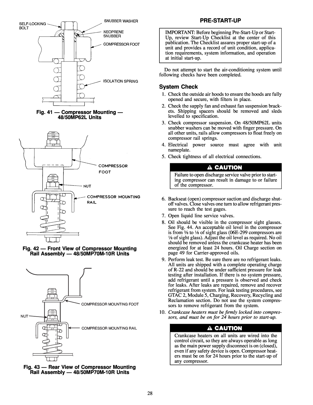
Fig. 41 Ð Compressor Mounting Ð
48/50MP62L Units
Fig. 42 Ð Front View of Compressor Mounting
Rail Assembly Ð 48/50MP70M-10R Units
COMPRESSOR MOUNTING FOOT
NUT ![]()
![]()
COMPRESSOR MOUNTING RAIL
Fig. 43 Ð Rear View of Compressor Mounting
Rail Assembly Ð
PRE-START-UP
IMPORTANT: Before beginning
Do not attempt to start the
System Check
1.Check the outside air hoods to ensure the hoods are fully opened and secure, with ®lters in place.
2.Check the supply fan and exhaust fan suspension brack- ets. Shipping spacers should be removed and sleds levelled to speci®cation.
3.Check compressor suspension. On 48/50MP62L units snubber washers can be moved with ®nger pressure. On all other units, rails allow compressors to ¯oat freely on compressor rail springs.
4.Electrical power source must agree with unit nameplate.
5.Check tightness of all electrical connections.
Failure to open discharge service valve prior to start- ing compressor can result in damage to or failure of the compressor.
6.Backseat (open) compressor suction and discharge shut- off valves. Close valves one turn to allow refrigerant pres- sure to reach the test gages.
7.Open liquid line service valves.
8.Oil should be visible in the compressor sight glasses. See Fig. 44. An acceptable oil level in the compressor is from 3¤8 to 1¤8 of sight glass
9.Perform leak test. Be sure there are no refrigerant leaks. All units are shipped with a complete operating charge of
10.Crankcase heaters must be ®rmly locked into compres- sors, and must be on for 24 hours prior to
Crankcase heaters on all units are wired into the control circuit, so they are always operable as long as the main power supply disconnect is on (closed), even if any safety device is open. Compressor heat- ers must be on for 24 hours prior to the
28