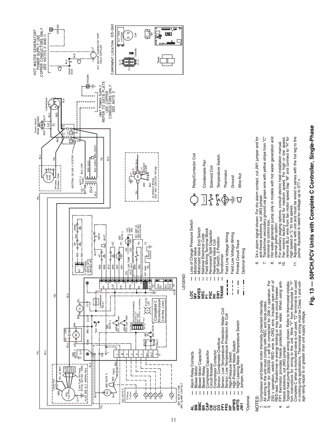
PCV015-060 specifications
The Carrier PCV015-060 is a cutting-edge packaged cooling and heating unit designed for commercial applications that demand high efficiency, reliability, and adaptability. This model is particularly renowned for its robust performance, making it an ideal choice for businesses seeking optimal indoor climate control.One of the standout features of the PCV015-060 is its impressive energy efficiency. Equipped with advanced scroll compressors, this unit operates with a higher energy efficiency ratio (EER), translating to lower operational costs and reduced environmental impact. The incorporation of eco-friendly refrigerants further bolsters its sustainability credentials, ensuring compliance with modern environmental regulations.
The PCV015-060 showcases superior airflow design, which minimizes noise levels while maximizing thermal comfort. Its high-efficiency evaporator and condenser coils facilitate enhanced heat transfer, ensuring effective cooling and heating performance even in extreme weather conditions. This model is also designed with multiple fan speed options, allowing users to customize air distribution according to specific requirements.
Built with user-friendly controls, the Carrier PCV015-060 supports advanced digital thermostat interfaces, enabling precise temperature management. Optional integration with building management systems allows for remote monitoring and control, enhancing operational efficiency and simplifying maintenance tasks.
Durability is another hallmark of the PCV015-060. The unit is constructed using high-quality materials designed to withstand varying environmental conditions, which enhances the lifespan of the system. Additionally, its modular design simplifies installation and service access, reducing downtime for businesses.
The versatility of the PCV015-060 is underscored by its capability to function effectively in numerous configurations, including rooftop installations and ground-mounted setups. It can efficiently handle diverse applications, from offices to retail spaces, making it an adaptable choice for many commercial needs.
In summary, the Carrier PCV015-060 offers a blend of energy efficiency, advanced technology, and durable construction, making it a formidable solution for businesses seeking reliable climate control. Its commitment to sustainability, user-friendly features, and versatile configurations solidify its standing as a premier choice for commercial heating and cooling needs. With the PCV015-060, businesses can ensure a comfortable environment for both employees and customers while maintaining operational efficiency.

