6Powering On the System
When all of the interfaces are connected, perform a visual check of all connections, and then check that:
•The ejector levers on each line card are in the locked position.
•All top and bottom line card captive screws are tight.
•All network interface cables are connected to the line cards.
•The console terminal is turned on.
•A Flash memory card is installed in the PRE.
If you have an AC power supply, the system has power after the power cord has been plugged into the facility VAC input receptacle.
You are now ready to power on the system for the first time using the following procedure:
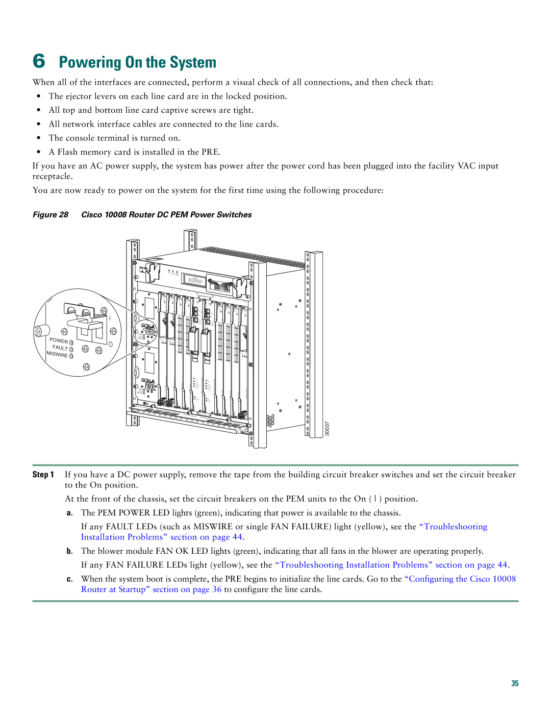
Figure 28 Cisco 10008 Router DC PEM Power Switches
POWER
FAULT  MISWIRE
POWER FAULT MISWIRE
POWER FAULT MISWIRE![]()
FANS | FAN |
|
|
|
|
|
|
|
|
|
OK | MUL |
|
|
|
|
|
|
|
| |
| FAILURE | FANTI- |
|
|
|
|
|
|
|
|
|
| FAILURE |
|
|
|
|
|
|
|
|
|
|
| When hot CAUTION |
|
|
|
|
| ||
|
|
| removal | swapping this |
|
|
|
|
| |
|
|
| be done andin replacementfan tray, |
|
|
| ||||
|
|
| system | under |
| must |
|
|
| |
|
|
|
| two minutes | or |
|
|
| ||
|
|
|
| shutdown will occur. |
|
|
| |||
1 | 2 |
|
|
|
|
|
|
|
|
|
| 3 |
|
|
|
|
|
|
|
| |
|
| 4 |
|
|
|
|
|
|
| |
|
|
| 0A |
|
|
|
|
| ||
10000 |
|
|
|
|
| 0B |
|
| ||
|
|
|
| PROCESSOR |
|
| ||||
CISCO | CISCO |
|
|
|
|
|
| ONLY |
|
|
| CISCO |
|
|
|
|
| 5 |
| ||
FAIL | 10000 |
|
|
|
|
|
|
| 6 | |
| FAIL | 10000 | CISCO |
| CISCO |
|
|
|
| |
|
| FAIL | 10000 |
|
|
|
|
|
| |
|
|
| FAIL |
| 10000 |
|
| CISCO |
|
|
|
|
|
|
|
|
|
| 10000 | CISCO |
|
|
|
|
|
|
|
|
|
| 10000 | CISCO |
|
|
|
|
|
|
|
|
|
| 10000 |
FAIL
FAIL
|
|
| CON |
|
|
|
|
|
|
|
|
| SOL |
| C |
|
|
| |
CA |
|
|
| E |
| ONS |
|
|
|
RRIEALARLO | CAR A |
| AU |
|
| OLE |
|
| |
0 R M OP | RIERLARMLOOP |
| X |
|
| AUX |
|
|
|
| 0 |
| AC |
|
|
|
|
|
|
|
|
| TIV |
|
|
| CA |
| |
|
|
| ET | ITY |
| AC |
| RRIEALARLO | CAR A |
| SLOTSLOT | LINHERNE |
| E TIVITY |
| R M OP | RIELARLO | ||
1 | 0 | 1 | K | T | SLOTSLOT | THERNE | 0 | R M OP | |
| 1 |
|
|
| 0 1 | LINK | T |
| 0 |
2 | 1 |
2 | 1 |
LIN |
| C | 3 | 2 |
K T | R | AR AL | 3 | 2 |
X | X | RIER ARMLOO |
|
|
P
4 |
| 3 |
4 |
| 3 |
5 |
| 4 |
5 |
| 4 |
|
| 5 |
|
| 5 |
A |
|
|
CO |
|
|
|
| A |
C |
| CO |
RIT |
| |
M | ICAL | CR |
AJO | ITIC | |
MI | R | MAJ AL |
NOR | OR | |
|
| MIN |
|
| OR |
S |
|
|
TATU |
| |
FA | S | STATUS |
IL | ||
|
| FAIL |
7 8
CISCO | CISCO |
10000 | |
| 10000 |
FAIL
FAIL
C
A
R A
L
R
A
LO
IE
R
RO
M
P
0 ![]()
1 |
2 |
3 |
|
| C |
| AR |
| RIE |
4 | R TX RX |
5 |
|
30037
Step 1 If you have a DC power supply, remove the tape from the building circuit breaker switches and set the circuit breaker to the On position.
At the front of the chassis, set the circuit breakers on the PEM units to the On ( ) position.
a.The PEM POWER LED lights (green), indicating that power is available to the chassis.
If any FAULT LEDs (such as MISWIRE or single FAN FAILURE) light (yellow), see the “Troubleshooting Installation Problems” section on page 44.
b.The blower module FAN OK LED lights (green), indicating that all fans in the blower are operating properly.
If any FAN FAILURE LEDs light (yellow), see the “Troubleshooting Installation Problems” section on page 44.
c.When the system boot is complete, the PRE begins to initialize the line cards. Go to the “Configuring the Cisco 10008 Router at Startup” section on page 36 to configure the line cards.
35