Attaching the Cable-Management Bracket
Use the following procedure to attach the
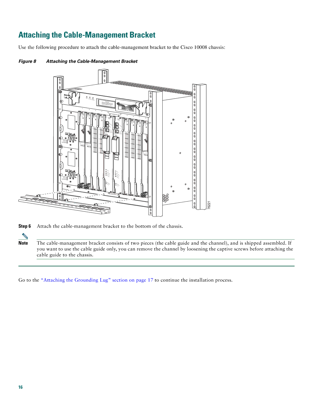
Figure 8 Attaching the Cable-Management Bracket
FANS | FAN |
|
OK | MFUALNTI- | |
| FAILURE | |
|
| FAILURE |
C |
| |
When hot swAUTION |
| |
removal and apping this | fan tray, | |
be done in | replacem | |
system shuunder two menint must | ||
| tdown will occur.utes or | |
POWER FAULT MISWIRE 
1 | 2 |
| |
CISCO | CISCO |
10000 | |
FA | 10000 |
IL | FAIL |
LIN |
|
K TX RX | CARRIER |
| ALARMLO |
O
P
3
CISCO 10000
F
A
IL
C
A
R A
RI LA L
E R O
RO
M
P
0
1
2
3
4
5
4 |
| 0A |
| |
|
|
| ||
|
|
| PROCESSOR | 0B |
CISCO |
|
|
| ONLY |
10000 |
| CISCO |
| |
FA |
| 1 | 0000 | CISCO |
IL |
|
| ||
|
|
|
| 10000 |
|
|
| C |
|
|
|
| ON |
|
|
|
| SOL | C |
|
|
| E | ON |
C |
|
| AU | SOL |
AR A |
|
| E | |
RIELA LO |
|
| X | AUX |
R RM OP |
|
|
| |
0 |
|
| AC |
|
|
|
| TIVI | ACTI |
|
|
| ETH TY | |
SLOT SLOT |
| LINKERNET | ETHVITY | |
0 | 1 |
| SLO SL | L ERN |
1 |
|
| T0 OT1 | INK ET |
2 |
|
|
|
|
3 |
|
|
|
|
4 |
|
|
|
|
5 |
|
|
|
|
| 5 | 6 |
|
|
|
| 7 |
| |
|
|
| 8 | |
|
|
|
| |
| CISCO | CISCO |
|
|
| 10000 | CISCO |
| |
| F | 10000 | CISCO | |
| AIL | AIL | 10000 | |
| F |
|
| |
|
|
| FA | 10000 |
|
|
| IL | F |
|
|
|
| AIL |
C |
|
|
|
|
AR A | C |
|
| |
RIELAR LO | AR A |
|
| |
0 | R M OP | RIERLARMLOOP | CARRIEALAR LO |
|
|
| 0 | R M OP |
|
|
|
| 0 |
|
1 |
| 1 |
|
|
|
|
|
| |
|
|
| 1 |
|
2 |
| 2 |
|
|
|
|
|
| |
|
|
| 2 |
|
3 |
| 3 |
|
|
|
|
|
| |
|
|
| 3 |
|
|
|
|
| C |
4AR
4RIE
POWER FAULT MISWIRE 
GIGABIT ETHERNET | CH |
| A |
| PERFORMANCEROUTING ENGINE |
|
| PERFORMANCEROUTING ENGINE |
| CO |
|
|
| ||
|
|
| A |
| ||
| C |
| CO |
| ||
| RITI |
|
| |||
MAJ | CA | C |
| |||
L | RITI | |||||
OR | M | CAL | ||||
MIN |
| AJO | ||||
OR | MIN | R | ||||
|
|
| ||||
|
| OR | ||||
|
|
|
| |||
| STAT |
|
|
|
| |
| F | US |
| STAT |
| |
| AIL |
|
|
| ||
|
|
|
| F | US |
|
|
|
|
| AIL |
|
|
|
| R | T | RX |
|
| 4 | X | |
5 | 5 |
|
|
|
|
|
|
| |
|
| 5 |
|
|
|
|
|
| OC– |
| ||||
|
|
|
| IR |
PROCESSOR ONLY
76221
Step 6 Attach the
Note The
Go to the “Attaching the Grounding Lug” section on page 17 to continue the installation process.
16