2Preparing for Installation
This section guides you through the process of preparing for your router installation.
Warning | Only trained and qualified personnel should be allowed to install or replace this equipment. Statement 49 |
Site Preparation
Before you install the Cisco 10008 router, consider:
•The power and cabling requirements that must be in place at your installation site
•The equipment required to install the router
•The environmental conditions your installation site must meet to maintain normal operation
Do not unpack the system until you are ready to install it. Keep the chassis in the shipping container to prevent accidental damage until you determine an installation site. Use the appropriate unpacking documentation included with the system.
Recommended Tools and Supplies
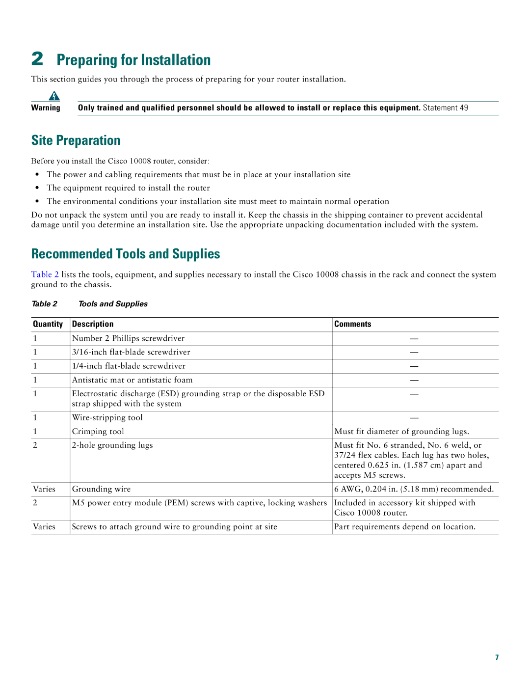
Table 2 lists the tools, equipment, and supplies necessary to install the Cisco 10008 chassis in the rack and connect the system ground to the chassis.
Table 2 | Tools and Supplies |
|
|
|
|
Quantity | Description | Comments |
|
|
|
1 | Number 2 Phillips screwdriver | — |
|
|
|
1 | — | |
|
|
|
1 | — | |
|
|
|
1 | Antistatic mat or antistatic foam | — |
|
|
|
1 | Electrostatic discharge (ESD) grounding strap or the disposable ESD | — |
| strap shipped with the system |
|
|
|
|
1 | — | |
|
|
|
1 | Crimping tool | Must fit diameter of grounding lugs. |
|
|
|
2 | Must fit No. 6 stranded, No. 6 weld, or | |
|
| 37/24 flex cables. Each lug has two holes, |
|
| centered 0.625 in. (1.587 cm) apart and |
|
| accepts M5 screws. |
|
|
|
Varies | Grounding wire | 6 AWG, 0.204 in. (5.18 mm) recommended. |
|
|
|
2 | M5 power entry module (PEM) screws with captive, locking washers | Included in accessory kit shipped with |
|
| Cisco 10008 router. |
|
|
|
Varies | Screws to attach ground wire to grounding point at site | Part requirements depend on location. |
|
|
|
7
