Appendix B Connector and Cable Specifications
Cables and Adapters
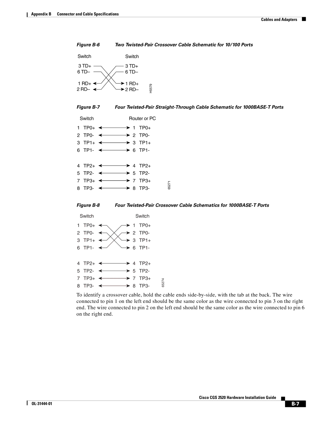
Figure B-6
Switch
3TD+ 6 TD–
1RD+ ![]() 2 RD–
2 RD– ![]()
Figure B-7
Switch
1 TP0+
2 TP0-
3 TP1+
6 TP1-
4 TP2+
5 TP2-
7 TP3+
8 TP3-
Figure B-8
Switch
1 TP0+
2 TP0-
3 TP1+
6 TP1-
4 TP2+
5 TP2-
7 TP3+
8 TP3-
Two
Switch
3TD+
6TD–
1 RD+ | H5579 | |
2 RD– | ||
|
Four
Router or PC |
| ||
1 | TP0+ |
| |
2 | TP0- |
| |
3 | TP1+ |
| |
6 | TP1- |
| |
4 | TP2+ |
| |
5 | TP2- |
| |
7 | TP3+ | 65271 | |
8 | TP3- | ||
| |||
Four
| Switch |
| |
1 | TP0+ |
| |
2 | TP0- |
| |
3 | TP1+ |
| |
6 | TP1- |
| |
4 | TP2+ |
| |
5 | TP2- |
| |
7 | TP3+ | 65274 | |
8 | TP3- | ||
|
To identify a crossover cable, hold the cable ends
Cisco CGS 2520 Hardware Installation Guide
| ||
|