Chapter 2 Switch Installation
Connecting Devices to the Ethernet Ports
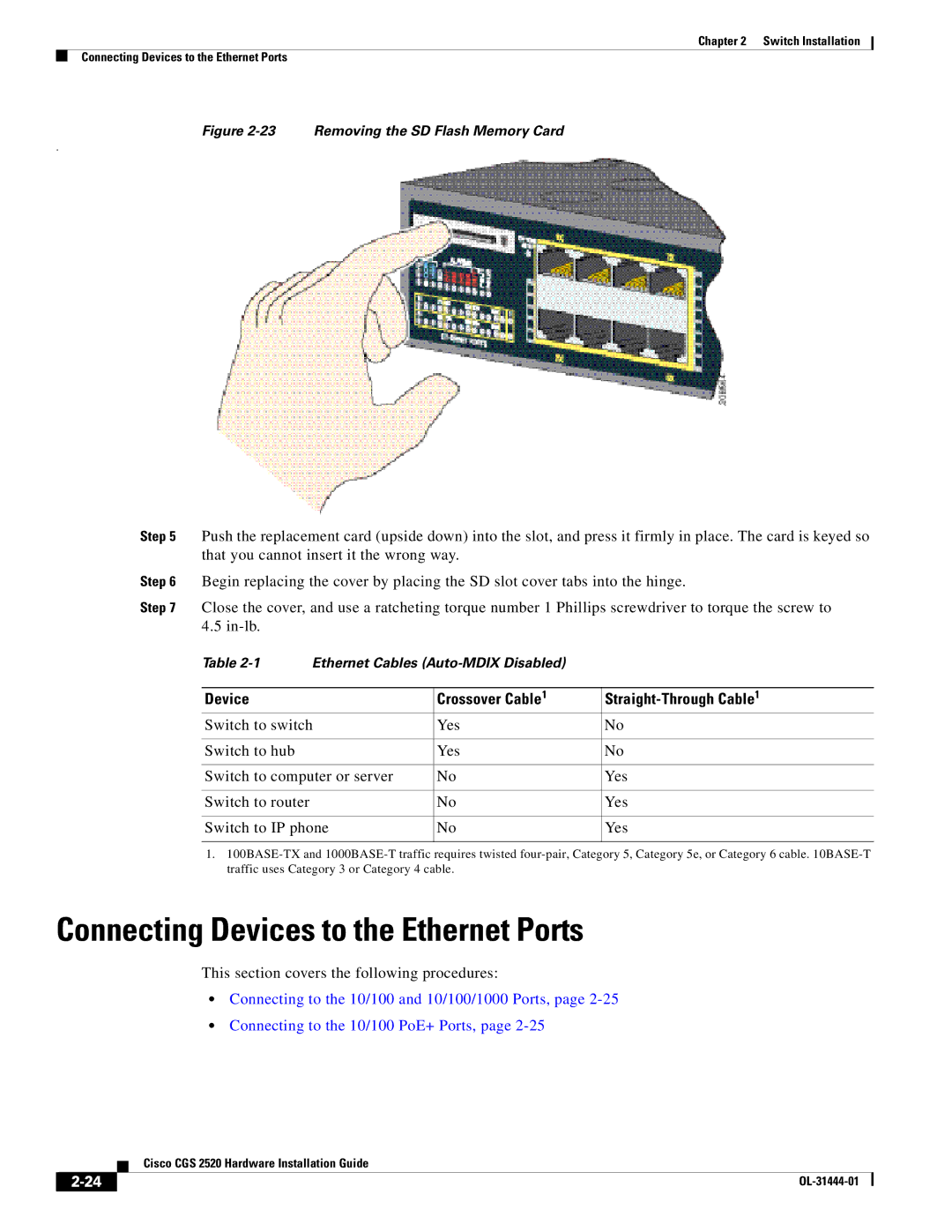
Figure 2-23 Removing the SD Flash Memory Card
.
Step 5 Push the replacement card (upside down) into the slot, and press it firmly in place. The card is keyed so that you cannot insert it the wrong way.
Step 6 | Begin replacing the cover by placing the SD slot cover tabs into the hinge. | |||
Step 7 | Close the cover, and use a ratcheting torque number 1 Phillips screwdriver to torque the screw to | |||
| 4.5 |
|
|
|
| Table | Ethernet Cables |
| |
|
|
|
|
|
| Device |
| Crossover Cable1 |
|
| Switch to switch | Yes | No | |
|
|
|
|
|
| Switch to hub |
| Yes | No |
|
|
|
| |
| Switch to computer or server | No | Yes | |
|
|
|
|
|
| Switch to router |
| No | Yes |
|
|
|
| |
| Switch to IP phone | No | Yes | |
|
|
|
|
|
1.
Connecting Devices to the Ethernet Ports
This section covers the following procedures:
•Connecting to the 10/100 and 10/100/1000 Ports, page
•Connecting to the 10/100 PoE+ Ports, page
| Cisco CGS 2520 Hardware Installation Guide |