IE 3000 Series, IEM30004PC specifications
The Cisco IEM30004PC is an integral component of the Cisco IE 3000 Series, designed specifically for deployment in harsh industrial environments. This managed Ethernet switch provides versatility, reliability, and robust performance necessary for industrial applications, supporting a range of Ethernet-enabled devices.One of the main features of the IEM30004PC is its rugged design. The switch is built to withstand extreme temperatures, vibrations, and electromagnetic interference, making it ideal for usage in manufacturing plants, oil and gas facilities, and transportation systems. It operates within a wide temperature range of -40 to 75 degrees Celsius, ensuring dependable functionality in varying environmental conditions.
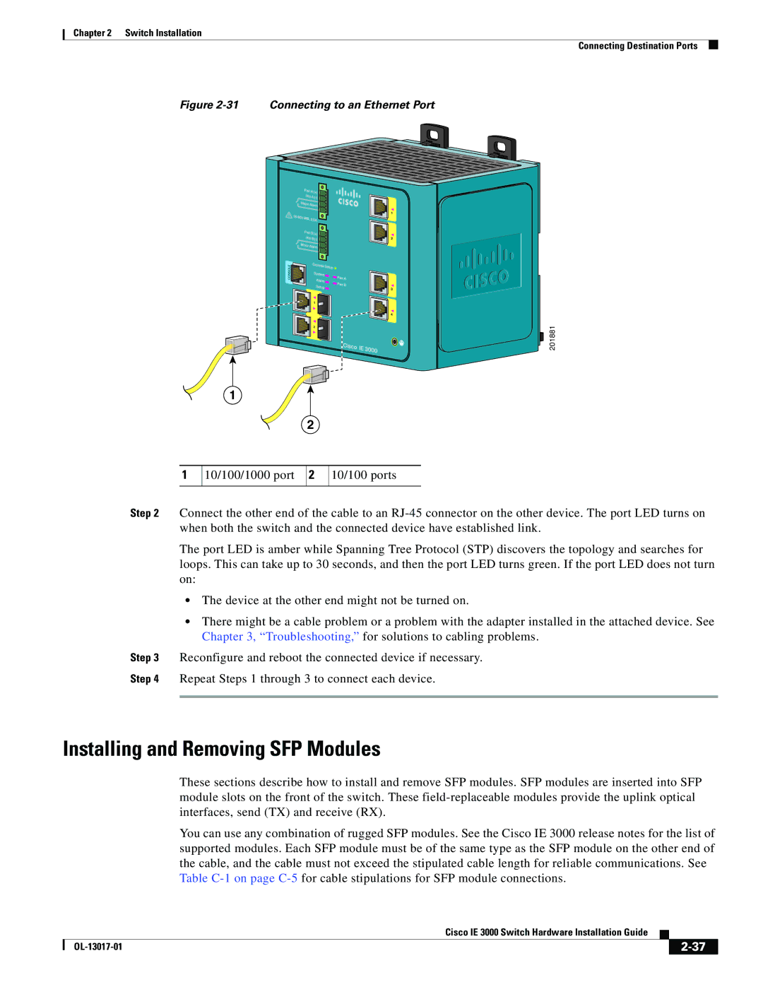
The IEM30004PC is equipped with four 10/100/1000 Gigabit Ethernet ports. These ports support both copper and fiber connections, providing flexibility for network installations. In addition, the switch supports various redundancy protocols, including Rapid Spanning Tree Protocol (RSTP) and Link Aggregation Control Protocol (LACP), which enhance network reliability and fault tolerance.
Another distinguishing characteristic of the IEM30004PC is its support for Power over Ethernet (PoE). This feature allows the switch to deliver power over the Ethernet cables to connected devices, such as IP cameras and wireless access points, eliminating the need for separate power sources and simplifying installations.
Cisco's IEM30004PC also integrates advanced security features, including 802.1X port-based authentication, Access Control Lists (ACLs), and Role-Based Access Control (RBAC). These security measures ensure that only authorized devices can connect to the network, reducing the risk of unauthorized access and enhancing overall network integrity.
For network management, the IEM30004PC supports Simple Network Management Protocol (SNMP), Cisco's Network Assistant, and other management tools. This enables centralized control and monitoring of the network, simplifying the administration and operation of industrial networks.
In summary, the Cisco IEM30004PC, as part of the IE 3000 Series, is engineered for robust performance in industrial settings. With its rugged design, multiple Gigabit Ethernet ports, PoE capabilities, and advanced security features, it is an excellent choice for organizations seeking reliable networking solutions in challenging environments. Its comprehensive management options further enhance its utility, making it an indispensable asset for modern industrial networks.

