Chapter 1 Overview

Front-Panel Description

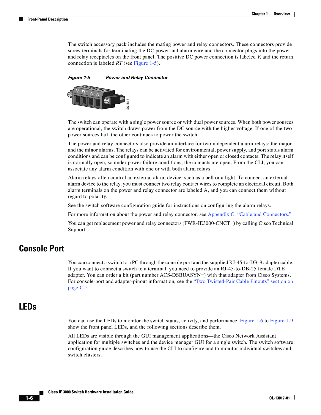
The switch accessory pack includes the mating power and relay connectors. These connectors provide screw terminals for terminating the DC power and alarm wire and the connector plugs into the power and relay receptacles on the front panel. The positive DC power connection is labeled V, and the return connection is labeled RT (see Figure 1-5).

Figure 1-5 Power and Relay Connector

201815

The switch can operate with a single power source or with dual power sources. When both power sources are operational, the switch draws power from the DC source with the higher voltage. If one of the two power sources fail, the other continues to power the switch.

The power and relay connectors also provide an interface for two independent alarm relays: the major and the minor alarms. The relays can be activated for environmental, power supply, and port status alarm conditions and can be configured to indicate an alarm with either open or closed contacts. The relay itself is normally open, so under power failure conditions, the contacts are open. From the CLI, you can associate any alarm condition with one or with both alarm relays.

Alarm relays often control an external alarm device, such as a bell or a light. To connect an external alarm device to the relay, you must connect two relay contact wires to complete an electrical circuit. Both alarm terminals on the power and relay connector are labeled A, and you can connect them without regard to polarity.

See the switch software configuration guide for instructions on configuring the alarm relays.

For more information about the power and relay connector, see Appendix C, “Cable and Connectors.”

You can get replacement power and relay connectors (PWR-IE3000-CNCT=) by calling Cisco Technical Support.

Console Port

You can connect a switch to a PC through the console port and the supplied RJ-45-to-DB-9 adapter cable. If you want to connect a switch to a terminal, you need to provide an RJ-45-to-DB-25 female DTE adapter. You can order a kit (part number ACS-DSBUASYN=) with that adapter from Cisco Systems. For console-port and adapter-pinout information, see the “Two Twisted-Pair Cable Pinouts” section on page C-5.

LEDs

You can use the LEDs to monitor the switch status, activity, and performance. Figure 1-6to Figure 1-9show the front panel LEDs, and the following sections describe them.

All LEDs are visible through the GUI management applications—the Cisco Network Assistant application for multiple switches and the device manager GUI for a single switch. The switch software configuration guide describes how to use the CLI to configure and to monitor individual switches and switch clusters.

Cisco IE 3000 Switch Hardware Installation Guide

1-6

OL-13017-01


Page 16
Image 16
Cisco Systems IEM30004PC, IE 3000 Series manual Console Port, LEDs

IE 3000 Series, IEM30004PC specifications

The Cisco IEM30004PC is an integral component of the Cisco IE 3000 Series, designed specifically for deployment in harsh industrial environments. This managed Ethernet switch provides versatility, reliability, and robust performance necessary for industrial applications, supporting a range of Ethernet-enabled devices.

One of the main features of the IEM30004PC is its rugged design. The switch is built to withstand extreme temperatures, vibrations, and electromagnetic interference, making it ideal for usage in manufacturing plants, oil and gas facilities, and transportation systems. It operates within a wide temperature range of -40 to 75 degrees Celsius, ensuring dependable functionality in varying environmental conditions.

The IEM30004PC is equipped with four 10/100/1000 Gigabit Ethernet ports. These ports support both copper and fiber connections, providing flexibility for network installations. In addition, the switch supports various redundancy protocols, including Rapid Spanning Tree Protocol (RSTP) and Link Aggregation Control Protocol (LACP), which enhance network reliability and fault tolerance.

Another distinguishing characteristic of the IEM30004PC is its support for Power over Ethernet (PoE). This feature allows the switch to deliver power over the Ethernet cables to connected devices, such as IP cameras and wireless access points, eliminating the need for separate power sources and simplifying installations.

Cisco's IEM30004PC also integrates advanced security features, including 802.1X port-based authentication, Access Control Lists (ACLs), and Role-Based Access Control (RBAC). These security measures ensure that only authorized devices can connect to the network, reducing the risk of unauthorized access and enhancing overall network integrity.

For network management, the IEM30004PC supports Simple Network Management Protocol (SNMP), Cisco's Network Assistant, and other management tools. This enables centralized control and monitoring of the network, simplifying the administration and operation of industrial networks.

In summary, the Cisco IEM30004PC, as part of the IE 3000 Series, is engineered for robust performance in industrial settings. With its rugged design, multiple Gigabit Ethernet ports, PoE capabilities, and advanced security features, it is an excellent choice for organizations seeking reliable networking solutions in challenging environments. Its comprehensive management options further enhance its utility, making it an indispensable asset for modern industrial networks.