Chapter 1 Product Overview
Front Panel Description
Management Port
The management port is used (in ROMMON mode only) to recover a switch software image that has been corrupted or destroyed due to a network catastrophe. This port is not active while the switch is operating normally.
You should designate one of the normalports on your switch as a management port, used for configuration and monitoring traffic. D o not connect the management port to this network, it is only intended to be used from a direct console connection.
SFP Module Ports
The switch uses Gigabit Ethernet SFP modules to establish
For more information about these SFP modules, refer to your SFP module documentation.
LEDs
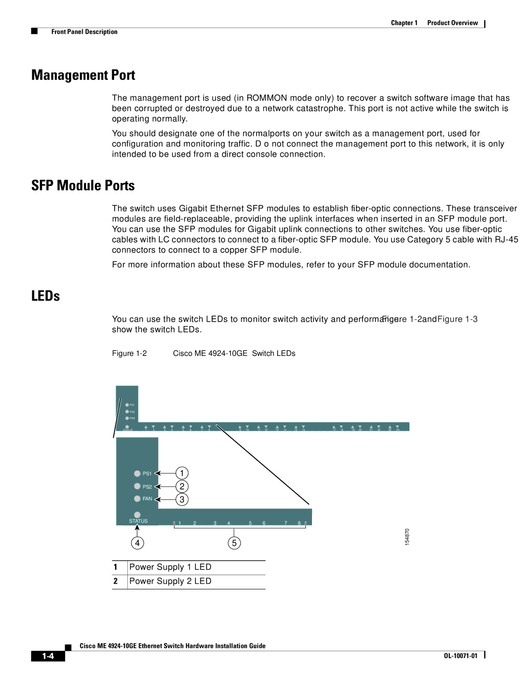
You can use the switch LEDs to monitor switch activity and performance. Figure
Figure 1-2 Cisco ME 4924-10GE Switch LEDs
![]() PS1
PS1
![]() PS2
PS2
![]() FAN
FAN
STATUS | 1 | 2 | 3 | 4 | 5 | 6 | 7 | 8 | 9 | 10 | 11 | 12 | 13 | 14 | 15 | 16 | 17 | 18 | 19 | 20 | 21 | 22 | 23 | 24 |
1
2
![]() PS1
PS1 ![]() 1
1
![]() PS2
PS2 ![]() 2
2
![]() FAN
FAN ![]() 3
3
STATUS | 1 | 2 | 3 | 4 | 5 | 6 | 7 | 8 |
|
45
Power Supply 1 LED
Power Supply 2 LED
154870
Cisco ME
|
| |
|