Chapter 2 Switch Installation
Preparing for Installation
•None (flow control)
Step 2 Use the supplied
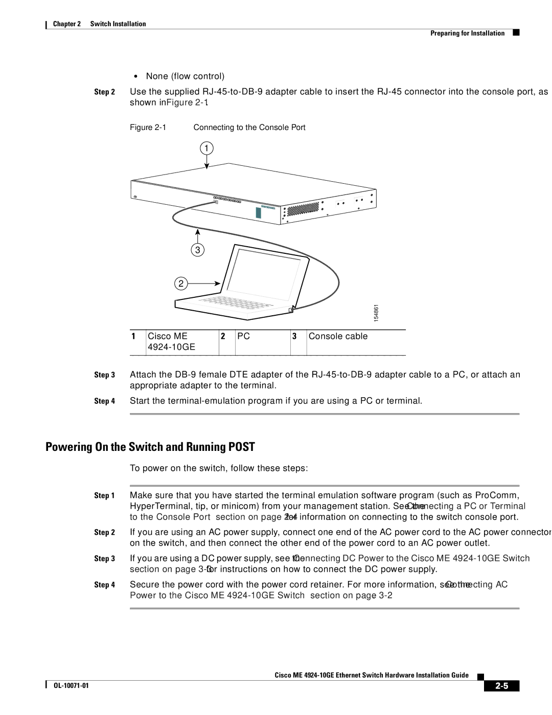
Figure 2-1 Connecting to the Console Port
1
13 | 14 | 15 | 16 | 17 | 18 |
|
|
|
|
|
|
|
|
|
| 19 | 20 | 21 | 22 |
|
| ||
|
|
|
|
|
|
|
| 23 | 24 |
Cisco ME
1
3
2
154861
Cisco ME | 2 | PC | 3 | Console cable |
|
|
|
| |
|
|
|
|
|
Step 3 Attach the
Step 4 Start the
Powering On the Switch and Running POST
To power on the switch, follow these steps:
Step 1 Make sure that you have started the terminal emulation software program (such as ProComm, HyperTerminal, tip, or minicom) from your management station. See the “Connecting a PC or Terminal to the Console Port” section on page
Step 2 If you are using an AC power supply, connect one end of the AC power cord to the AC power connector on the switch, and then connect the other end of the power cord to an AC power outlet.
Step 3 If you are using a DC power supply, see the “Connecting DC Power to the Cisco ME
Step 4 Secure the power cord with the power cord retainer. For more information, see the “Connecting AC Power to the Cisco ME
Cisco ME
|
| ||
|
|