Chapter 1 Product Overview
Front Panel Description
Optical Support
The switch supports Gigabit Ethernet SFP modules as described at these URLs:
•http://www.cisco.com/en/US/products/hw/modules/ps5455/products_device_support_table09186a00 80446625.html
•http://www.cisco.com/en/US/products/hw/modules/ps5455/products_device_support_table09186a00 80385874.html
The switch supports X2 modules as described at this URL:
•http://www.cisco.com/en/US/products/hw/modules/ps5455/products_device_support_table09186a00 803857e7.html
Front Panel Description
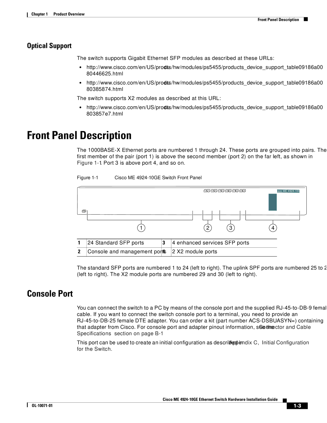
The
Figure 1-1 Cisco ME 4924-10GE Switch Front Panel
13 | 14 | 15 | 16 | 17 | 18 | 19 | 20 | 21 | 22 | 23 | 24 |
Cisco ME
| 1 |
| 2 | 3 | 4 |
|
|
|
|
|
|
1 | 24 Standard SFP ports | 3 | 4 enhanced services SFP ports |
| |
|
|
|
|
|
|
2 | Console and management ports | 4 | 2 X2 module ports |
|
|
|
|
|
|
|
|
The standard SFP ports are numbered 1 to 24 (left to right). The uplink SPF ports are numbered 25 to 28 (left to right). The X2 module ports are numbered 29 and 30 (left to right).
Console Port
You can connect the switch to a PC by means of the console port and the supplied
This port can be used to create an initial configuration as described in Appendix C, “Initial Configuration for the Switch.”
Cisco ME
|
| ||
|
|
