Chapter 2 Switch Installation
Connecting to an SFP Module
Step 4 Observe the port status LED.
The LED turns green when the switch and the target device have an established link.
If the LED is amber or off, the target device might not be turned on, there might be a cable problem, or there might be problem with the adapter installed in the target device. See Chapter 4, “Troubleshooting,” for solutions to cabling problems.
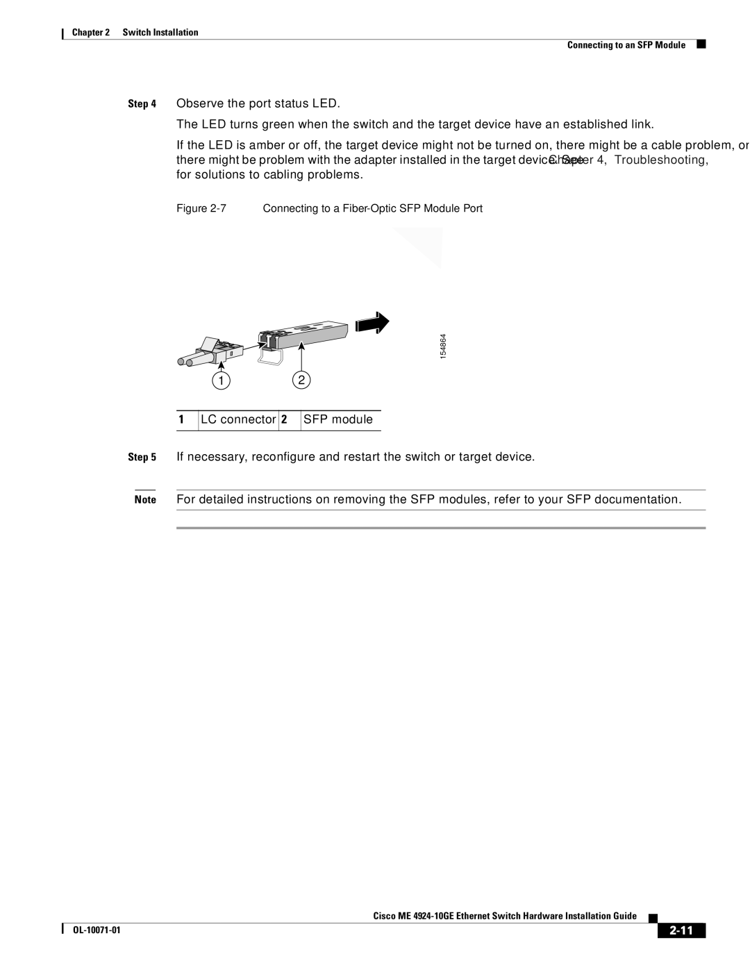
Figure 2-7 Connecting to a Fiber-Optic SFP Module Port
PS1
PS2
FAN
154864
1 2
1
LC connector
2
SFP module
Step 5 If necessary, reconfigure and restart the switch or target device.
Note For detailed instructions on removing the SFP modules, refer to your SFP documentation.
|
| Cisco ME |
|
| |
|
|
| |||
|
|
|
| ||
|
|
|
| ||