Chapter 2 Switch Installation
Installing and Removing SFP Modules
Mounting the Switch in a Rack
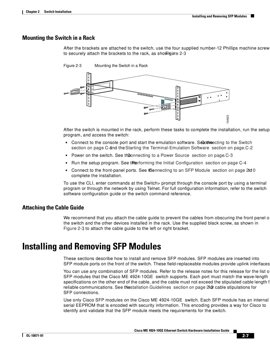
After the brackets are attached to the switch, use the four supplied
Figure 2-3 Mounting the Switch in a Rack
13 | 14 | 15 | 16 |
|
|
|
|
|
|
|
|
|
| 17 | 18 |
|
|
|
|
|
| ||
|
|
|
|
|
| 19 | 20 | 21 | 22 |
|
|
|
|
|
|
|
|
|
| 23 | 24 |
Cisco ME
154923
After the switch is mounted in the rack, perform these tasks to complete the installation, run the setup program, and access the switch:
•Connect to the console port and start the emulation software. See the “Connecting to the Switch” section on page
•Power on the switch. See the “Connecting to a Power Source” section on page
•Run the setup program. See the “Performing the Initial Configuration” section on page
•Connect to the
To use the CLI, enter commands at the Switch> prompt through the console port by using a terminal program or through the network by using Telnet. For full configuration information, refer to the switch software configuration guide or the switch command reference.
Attaching the Cable Guide
We recommend that you attach the cable guide to prevent the cables from obscuring the front panel of the switch and the other devices installed in the rack. Use the supplied black screw, as shown in Figure
Installing and Removing SFP Modules
These sections describe how to install and remove SFP modules. SFP modules are inserted into
SFP module ports on the front of the switch. These
You can use any combination of SFP modules. Refer to the release notes for this release for the list of SFP modules that the Cisco ME
Use only Cisco SFP modules on the Cisco ME
Cisco ME
|
| ||
|
|
