Chapter 1 Product Overview
Front Panel Description
3
4
5
FAN LED
STATUS LED
Port LED
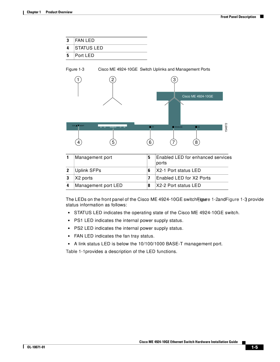
Figure 1-3 Cisco ME 4924-10GE Switch Uplinks and Management Ports
1 | 2 | 3 |
Cisco ME
|
|
|
|
|
|
|
|
|
|
|
|
|
|
CON | MGMT |
|
|
|
|
|
|
|
|
|
|
|
|
|
| 25 26 | ENABLED | 27 28 |
| 29 |
| ENABLED | 30 | ||||
|
|
|
|
|
|
|
|
|
|
|
|
|
|
4 | 5 | 6 | 7 | 8 |
154872
1 | Management port | 5 | Enabled LED for enhanced services |
|
|
| ports |
|
|
|
|
2 | Uplink SFPs | 6 | |
|
|
|
|
3 | X2 ports | 7 | Enabled LED for X2 Ports |
|
|
|
|
4 | Management port LED | 8 | |
|
|
|
|
The LEDs on the front panel of the Cisco ME
•STATUS LED indicates the operating state of the Cisco ME
•PS1 LED indicates the internal power supply status.
•PS2 LED indicates the internal power supply status.
•FAN LED indicates the fan tray status.
•A link status LED is below the 10/100/1000
Table
Cisco ME
|
| ||
|
|
