Chapter 2 Installing the Cisco Nexus 3000 Series Switches
Installing the Switch
Se n d d o c u m e n t c o m m e n t s t o n ex u s 3 k - d o c f e e d b a ck @ c i sc o . c o m
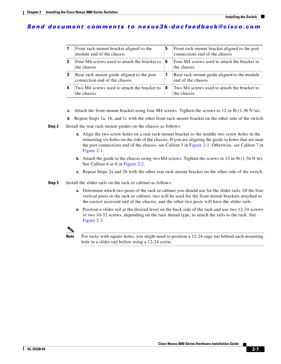
1 | Front | 5 | Front |
| module end of the chassis |
| connections end of the chassis |
|
|
|
|
2 | Four M4 screws used to attach the bracket to | 6 | Four M4 screws used to attach the bracket to |
| the chassis |
| the chassis |
|
|
|
|
3 | Rear | 7 | Rear |
| connection end of the chassis |
| end of the chassis |
|
|
|
|
4 | Two M4 screws used to attach the bracket to | 8 | Two M4 screws used to attach the bracket to |
| the chassis |
| the chassis |
|
|
|
|
c. Attach the
Step 2
a. Align the two screw holes on a rear
b. Attach the guide to the chassis using two M4 screws. Tighten the screws to 12
c. Repeat Steps 2a and 2b with the other rear
Step 3 | Install the slider rails on the rack or cabinet as follows: |
|
| |||
|
|
| a. Determine which two posts of the rack or cabinet you should use for the slider rails. Of the four | |||
|
|
|
| vertical posts in the rack or cabinet, two will be used for the front mount brackets attached to | ||
|
|
|
| the easiest accessed end of the chassis, and the other two posts will have the slider rails. |
|
|
|
|
| a. Position a slider rail at the desired level on the back side of the rack and use two | |||
|
|
|
| or two | ||
|
|
|
| Figure | · |
|
| Note |
| For racks with square holes, you might need to position a | |||
|
|
|
| hole in a slider rail before using a |
| · |
Cisco Nexus 3000 Series Hardware Installation Guide
|
| ||
|
|
