Chapter 2 Installing the Cisco Nexus 3000 Series Switches
Installing the Switch
Se n d d o c u m e n t c o m m e n t s t o n ex u s 3 k - d o c f e e d b a ck @ c i sc o . c o m
Table
Table | Cisco Nexus 3016, 3048, and 3064 Switch |
|
|
Quantity | Part Description |
|
|
2 | Front |
|
|
2 | Rear |
|
|
2 | Slider rails |
|
|
12 | M4 x 0.7 x |
|
|
Note You must supply the eight
To install the switch in a rack or cabinet, follow these steps:
Step 1 Install the front
a.Determine whether the chassis port connections or the fan tray and power supply modules should have easier access at the opening of the rack or cabinet. You will install that end of the chassis closest to the opening of the rack or cabinet.
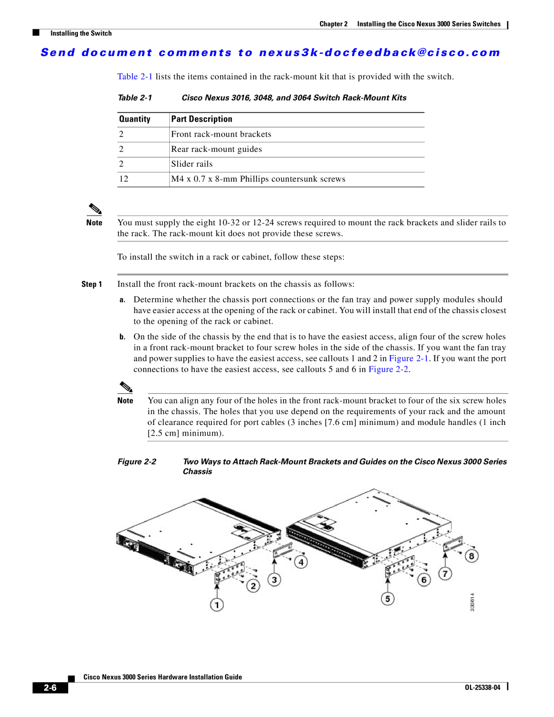
b.On the side of the chassis by the end that is to have the easiest access, align four of the screw holes in a front
Note You can align any four of the holes in the front
Figure | Two Ways to Attach |
| Chassis |
Cisco Nexus 3000 Series Hardware Installation Guide
| ||
|