Chapter 2 Installing the Cisco Nexus 3000 Series Switches
Grounding the Switch
Se n d d o c u m e n t c o m m e n t s t o n ex u s 3 k - d o c f e e d b a ck @ c i sc o . c o m
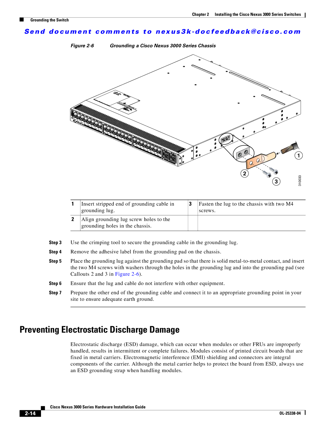
Figure 2-6 Grounding a Cisco Nexus 3000 Series Chassis
2
3
1
310033
1 | Insert stripped end of grounding cable in | 3 | Fasten the lug to the chassis with two M4 |
| grounding lug. |
| screws. |
|
|
|
|
2 | Align grounding lug screw holes to the |
|
|
| grounding holes in the chassis. |
|
|
|
|
|
|
Step 3 Use the crimping tool to secure the grounding cable in the grounding lug.
Step 4 Remove the adhesive label from the grounding pad on the chassis.
Step 5 Place the grounding lug against the grounding pad so that there is solid
Step 6 Ensure that the lug and cable do not interfere with other equipment.
Step 7 Prepare the other end of the grounding cable and connect it to an appropriate grounding point in your site to ensure adequate earth ground.
Preventing Electrostatic Discharge Damage
Electrostatic discharge (ESD) damage, which can occur when modules or other FRUs are improperly handled, results in intermittent or complete failures. Modules consist of printed circuit boards that are fixed in metal carriers. Electromagnetic interference (EMI) shielding and connectors are integral components of the carrier. Although the metal carrier helps to protect the board from ESD, always use an ESD grounding strap when handling modules.
| Cisco Nexus 3000 Series Hardware Installation Guide |