Chapter 3 Installing and Removing AC- and
Step 3 Align the two captive screws with the screw holes in the panel. Use a ratcheting torque screwdriver to torque each screw to 10
Step 4 Connect the
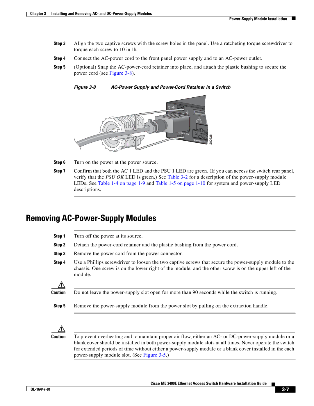
Step 5 (Optional) Snap the
Figure 3-8 AC-Power Supply and Power-Cord Retainer in a Switch
| 280828 |
Step 6 | Turn on the power at the power source. |
Step 7 | Confirm that both the AC 1 LED and the PSU 1 LED are green. (If you can access the switch rear panel, |
| verify that the PSU OK LED is green.) See Table |
| LEDs. See Table |
| descriptions. |
Removing AC-Power-Supply Modules
Step 1 Turn off the power at its source.
Step 2 Detach the
Step 3 Remove the power cord from the power connector.
Step 4 Use a Phillips screwdriver to loosen the two captive screws that secure the
Caution Do not leave the
Step 5 Remove the
Caution To prevent overheating and to maintain proper air flow, either an AC- or
Cisco ME 3400E Ethernet Access Switch Hardware Installation Guide
|
| ||
|
|
