Chapter 3 Installing and Removing AC- and
Caution To make sure that the equipment is reliably connected to earth ground, follow the grounding procedure instructions, and use a
Follow these steps to install either a
Step 1 Locate the ground adaptor and the
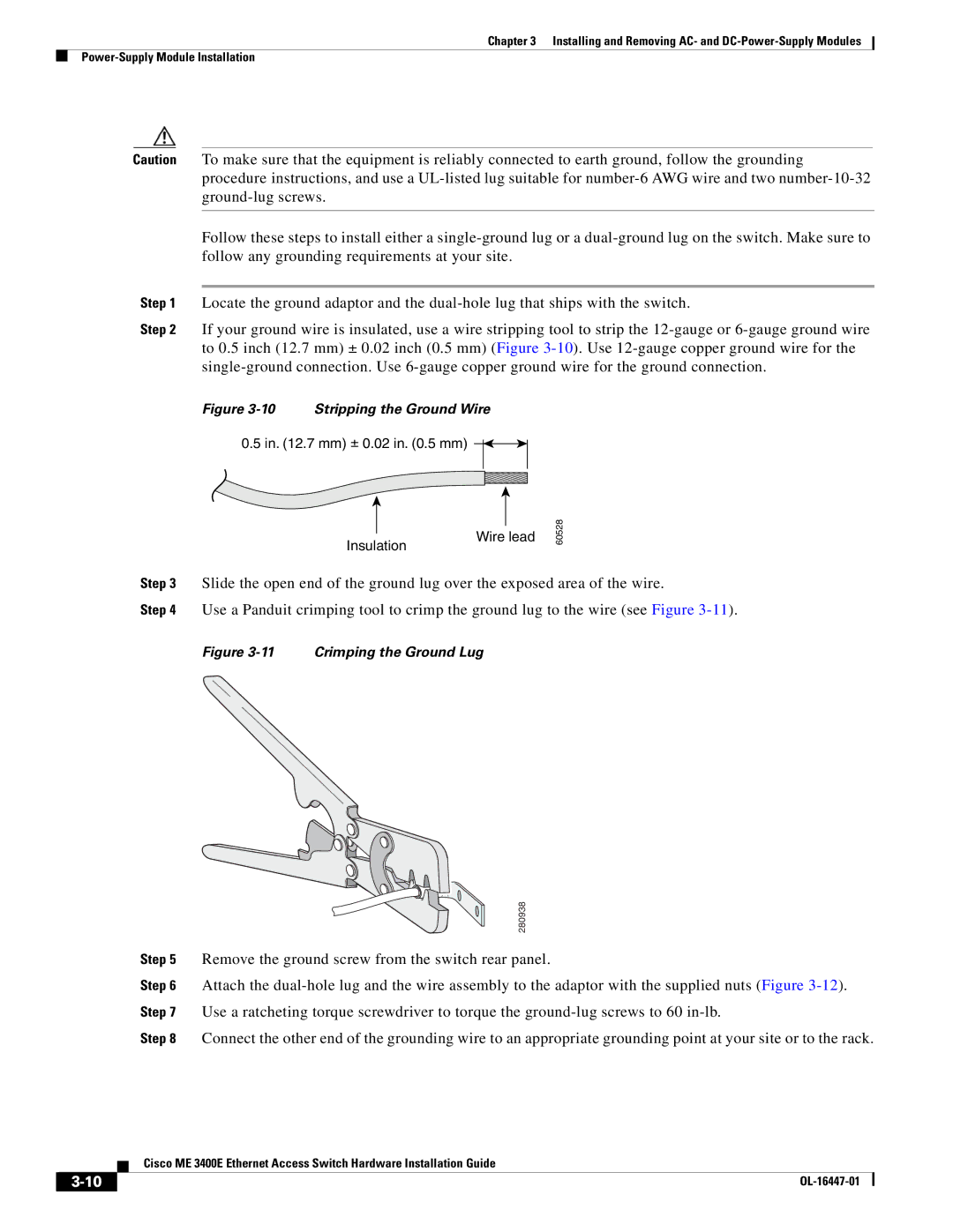
Step 2 If your ground wire is insulated, use a wire stripping tool to strip the
Figure 3-10 Stripping the Ground Wire
0.5 in. (12.7 mm) ± 0.02 in. (0.5 mm)
Insulation
Wire lead
60528
Step 3 Slide the open end of the ground lug over the exposed area of the wire.
Step 4 Use a Panduit crimping tool to crimp the ground lug to the wire (see Figure
Figure 3-11 Crimping the Ground Lug
| 280938 |
Step 5 | Remove the ground screw from the switch rear panel. |
Step 6 | Attach the |
Step 7 | Use a ratcheting torque screwdriver to torque the |
Step 8 | Connect the other end of the grounding wire to an appropriate grounding point at your site or to the rack. |
| Cisco ME 3400E Ethernet Access Switch Hardware Installation Guide |
|