Cisco Systems OL-16447-01 manual Removing the DC-Power-Supply Module, 3-16

Models: OL-16447-01

1 102
Download 102 pages 41.83 Kb
Page 68
Image 68
Figure 3-22 DC-Power Terminal Block With Two Feeds

Chapter 3 Installing and Removing AC- and DC-Power-Supply Modules

Power-Supply Module Installation

Step 12 Confirm that both the DCA LED and the PSU 1 LEDs are green. (If you can access the switch rear panel, verify that the
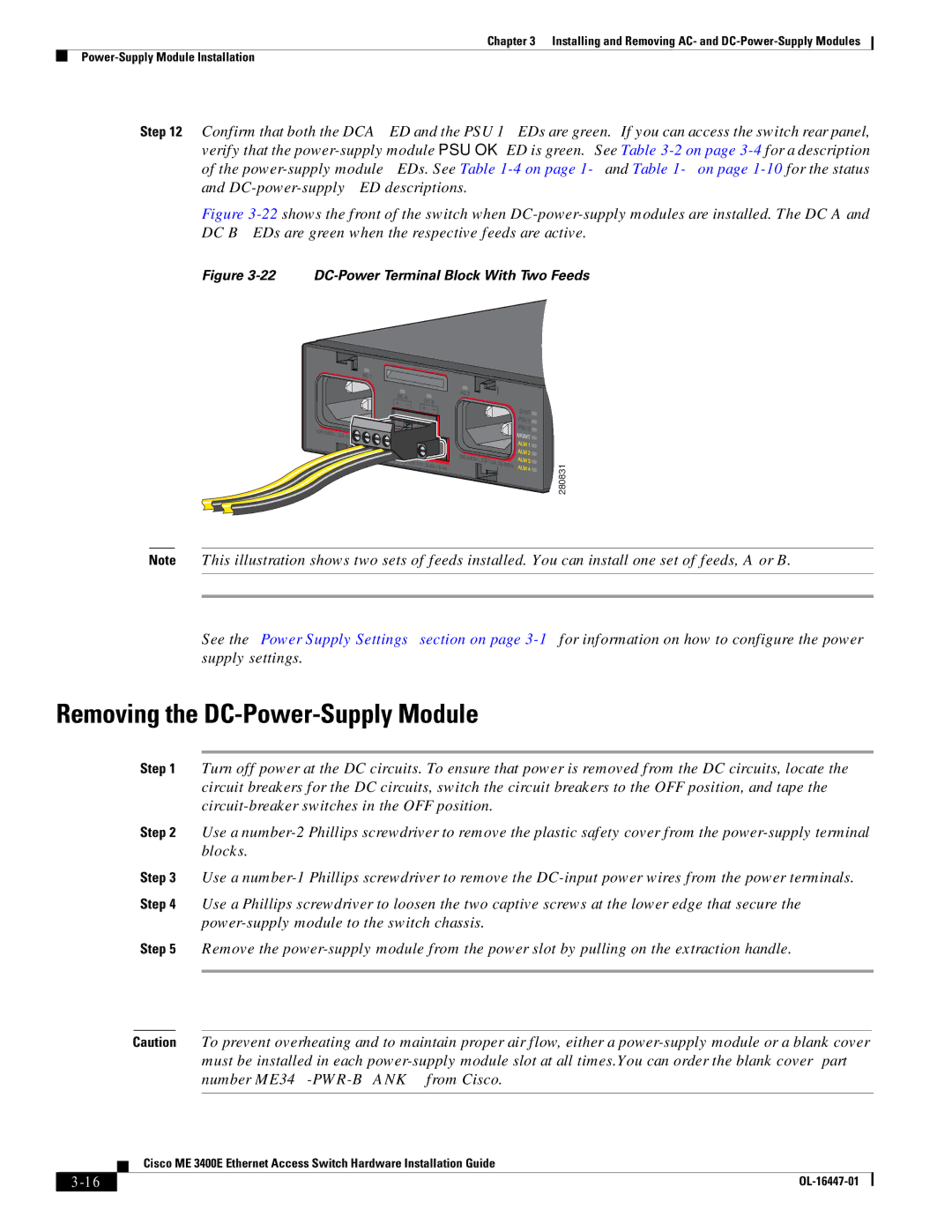
 power-supply module PSU OK LED is green.) See Table 3-2 on page 3-4for a description of the power-supply module LEDs. See Table 1-4 on page 1-9and Table 1-6 on page 1-10for the status and DC-power-supply LED descriptions.

Figure 3-22shows the front of the switch when DC-power-supply modules are installed. The DC A and DC B LEDs are green when the respective feeds are active.

Figure 3-22 DC-Power Terminal Block With Two Feeds

280831

Note This illustration shows two sets of feeds installed. You can install one set of feeds, A or B.

See the “Power Supply Settings” section on page 3-17for information on how to configure the power supply settings.

Removing the DC-Power-Supply Module

Step 1 Turn off power at the DC circuits. To ensure that power is removed from the DC circuits, locate the circuit breakers for the DC circuits, switch the circuit breakers to the OFF position, and tape the circuit-breaker switches in the OFF position.

Step 2 Use a number-2 Phillips screwdriver to remove the plastic safety cover from the power-supply terminal blocks.

Step 3 Use a number-1 Phillips screwdriver to remove the DC-input power wires from the power terminals.

Step 4 Use a Phillips screwdriver to loosen the two captive screws at the lower edge that secure the power-supply module to the switch chassis.

Step 5 Remove the power-supply module from the power slot by pulling on the extraction handle.

Caution To prevent overheating and to maintain proper air flow, either a power-supply module or a blank cover must be installed in each power-supply module slot at all times.You can order the blank cover (part number ME34X-PWR-BLANK=) from Cisco.


Cisco ME 3400E Ethernet Access Switch Hardware Installation Guide

3-16

OL-16447-01

Page 68
Image 68
Cisco Systems OL-16447-01 manual Removing the DC-Power-Supply Module, 3-16, 22 DC-Power Terminal Block With Two Feeds