800 553-NETS Fax 408
February
Cisco Systems, Inc 170 West Tasman Drive San Jose, CA
Cisco ME 3400E Ethernet Access Switch Hardware Installation Guide
Reorient or relocate the receiving antenna
Alarm Input Port
Obtaining Documentation and Submitting a Service Request
Switch Models
Alarm LEDs
Verifying Switch Operation
Installing the Switch
Installing and Removing SFP Modules
Mounting the Switch on a Wall
Clearing the Switch IP Address and Configuration
Troubleshooting
Port and Interface Settings
Switch LEDs
Contents
IP Settings C-2
Completing the Setup Program C-2
Cisco ME 3400E Ethernet Access Switch Hardware Installation Guide
Preface
Audience
Purpose
Cisco ME 3400E Ethernet Access Switch Command Reference
Release Notes for the Cisco ME 3400E Ethernet Access Switch
Cisco ME 3400E Ethernet Access Switch Software Configuration Guide
Cisco ME 3400E Ethernet Access Switch Hardware Installation Guide
Obtaining Documentation and Submitting a Service Request
Cisco Small Form-Factor Pluggable Modules Compatibility Matrix
Preface Obtaining Documentation and Submitting a Service Request
Cisco ME 3400E Ethernet Access Switch Hardware Installation Guide
OL-16447-01
Setting Up the Switch, page Switch Models, page Front Panel, page
Setting Up the Switch
Switch Models
Rear Panel, page Power Supply Features, page Fans, page
Front Panel
Switch Model
Description
Figure 1-2 Cisco ME 3400EG-12CS-M Front Panel
AC- and DC-Power Input Connectors
Alarm Input Port
Figure 1-3 Cisco ME 3400EG-2CS-A Front Panel
Dual-Purpose Ports
Management Port
10/100 Fast Ethernet Ports
SFP Modules
SFP Module Patch Cable
UNIs, NNIs, and ENIs
Switch LED Panels, page Power-Supply Module LEDs, page
Ethernet Management Port LED, page Alarm LEDs, page Port LEDs, page
LEDs
Switch LED Panels
Color
System Status
PSU 1 and PSU 2 Power-Supply LEDs
Power-Supply Module LEDs
Figure 1-7 Switch Power-Supply LEDs
System LED continued
AC-Power-Supply LEDs
Ethernet Management Port LED
1-10
DC-Power-Supply LEDs
Dual-Purpose Port LEDs
Alarm LEDs
Port LEDs
1-11
Rear Panel
1-12
Figure 1-8 Example of the Switch Dual-Purpose Port LEDs
Power Supply Features
1-13
1-14
Fans
Management Options
Chassis Airflow
Network Configurations
1-15
Chapter 1 Product Overview Management Options
1-16
Cisco ME 3400E Ethernet Access Switch Hardware Installation Guide
OL-16447-01
Verifying Switch Operation, page Installing the Switch, page
Switch Installation
Warnings, page Installation Guidelines, page
Installing and Removing SFP Modules, page
Warning Class 1 laser product. Statement
Warning No user-serviceable parts inside. Do not open. Statement
Installation Guidelines
149F 65C Statement
140F 60C Statement
Powering Off the Switch
Verifying Switch Operation
Installing the Switch
Rack-Mounting, page Wall-Mounting, page
Attaching Brackets to the Switch, page Mounting in a Rack, page
Removing Screws from the Switch
Removing Screws from the Switch, page
Rack-Mounting
Attaching Brackets to the Switch
Attaching Brackets for 19-Inch Racks
Figure 2-5 Attaching Brackets for 19-Inch, 23-Inch, and 24-Inch Racks
Chapter 2 Switch Installation Installing the Switch
Cisco ME 3400E Ethernet Access Switch Hardware Installation Guide
OL-16447-01
Attaching Brackets for 23-Inch Racks
2-10
Figure 2-6 Attaching Brackets for 23-Inch Racks
Attaching Brackets for 24-Inch Racks
2-11
Figure 2-7 Attaching Brackets for 24-Inch Racks
Chapter 2 Switch Installation Installing the Switch
Attaching Brackets for ETSI Racks
2-12
Cisco ME 3400E Ethernet Access Switch Hardware Installation Guide
Mounting in a Rack
2-13
Attaching Brackets for Wall-Mounting
Mounting the Switch on a Wall, page
Wall-Mounting
Attaching Brackets for Wall-Mounting, page
Mounting the Switch on a Wall
2-15
Phillips flat-head screw
Chapter 2 Switch Installation Installing the Switch
Cisco ME 3400EG-12CS-M
2-16
Cisco ME 3400E Ethernet Access Switch Hardware Installation Guide
Chapter 2 Switch Installation Installing the Switch
Cisco ME 3400E-24TS-M
2-17
Cisco ME 3400E Ethernet Access Switch Hardware Installation Guide
Cisco ME 3400EG-2CS-A
2-18
Figure 2-15 Mounting the Cisco ME 3400EG-2CS-A on a Wall
Table- or Shelf-Mounting
Installing and Removing SFP Modules
Installing SFP Modules
2-19
2-20
Step 5 Insert the cable connector into the SFP module
Inserting and Removing the SFP Module Patch Cable
Removing SFP Modules
2-21
Connecting to the 10/100 and 10/100/1000 Ports
Removing the SFP Module Patch Cable
2-22
2-23
Step 3 Reconfigure and reboot the connected device, if necessary
Connecting to Fiber-Optic SFP Modules
2-24
Connecting to 1000BASE-T SFP Modules
2-25
Figure 2-23 Connecting to a 1000BASE-T SFP Module
2-26
Connecting to Dual-Purpose Ports
Where to Go Next
Figure 2-24 Connecting to a Dual-Purpose Port
Product Overview, page Power-Supply Module Installation, page
Installing and Removing AC- and DC-Power-Supply Modules
Power-Supply Module Description
Power Supply Settings, page
Handle-Side Description
Figure 3-2 80-W DC-Power-Supply Module Handle Side
PSU OK
Figure 3-3 DC-Voltage Selector
Tools and Equipment, page Installation Guidelines, page
Power-Supply Module Installation
Connector-Side Description
Installing an AC-Power-Supply Module, page
Installation Guidelines
Tools and Equipment
Installing an AC-Power-Supply Module
AC-1 PSU-1 AC-2 PSU-2
Removing AC-Power-Supply Modules
3. Installing the DC-Power-Supply Module in the Switch, page
Installing a DC-Power-Supply Module
1. Preparing for Installation, page 2. Grounding the Switch, page
4. Wiring the DC-Input Power Source, page
Preparing for Installation
Grounding the Switch
Figure 3-9 DC-Power-Supply Diagram
3-10
Remove the ground screw from the switch rear panel
Figure 3-12 Attaching the Ground Lug and Wire Assembly
Installing the DC-Power-Supply Module in the Switch
3-11
Figure 3-13 Inserting a DC-Power-Supply Module
Wiring the DC-Input Power Source
10 A Statement
3-12
3-13
Step 2 Locate the terminal block plug see Figure
3-14
Return positive Feed A
3-15
Figure 3-21 Inserting the Terminal Block in the Block Header
Removing the DC-Power-Supply Module
3-16
Figure 3-22 DC-Power Terminal Block With Two Feeds
Power Supply Settings
3-17
Power Supply Settings
3-18
Chapter 3 Installing and Removing AC- and
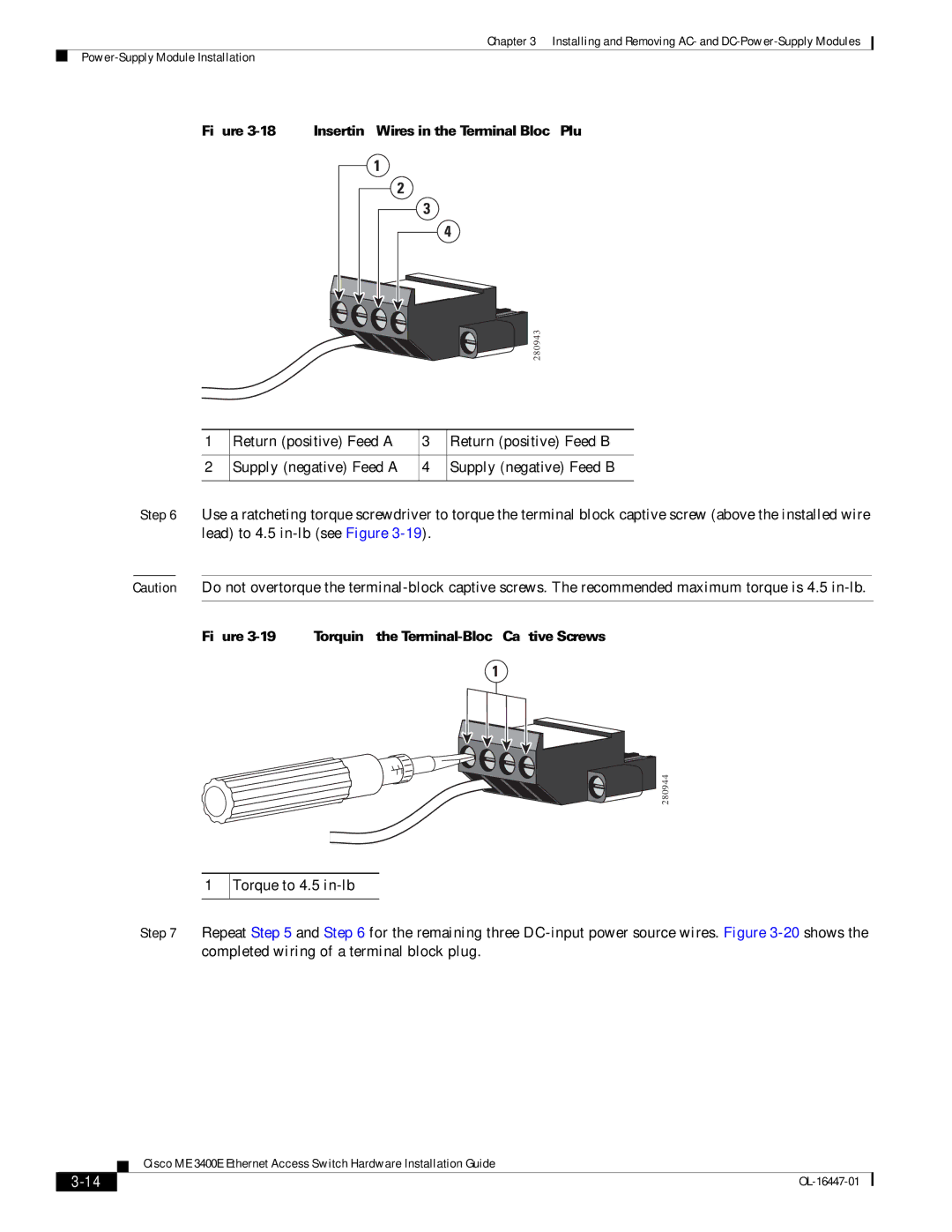
 DC-Power-Supply Modules
Cisco ME 3400E Ethernet Access Switch Hardware Installation Guide
Switch POST Results
Troubleshooting
Diagnosing Problems
Diagnosing Problems, page
Bad or Damaged Cable
Switch LEDs
Switch Connections
Ethernet and Fiber Cables
Ping the End Device
SFP Module Port Issues
Port and Interface Settings
Spanning Tree Loops
Speed, Duplex, and Autonegotiation
Clearing the Switch IP Address and Configuration
Switch Performance
Autonegotiation and NICs
Finding the Switch Serial Number
Appendix 4 Troubleshooting Finding the Switch Serial Number
Cisco ME 3400E Ethernet Access Switch Hardware Installation Guide
OL-16447-01
Environmental Ranges and Technical Specifications for the Switch
Technical Specifications
Environmental Ranges and Technical Specifications for the Switch
A P P E N D I X A
32 to 131F 0 to 55C
32 to 140F 0 to 60C
Operating Temperatures for the Cisco ME 3400EG-12CS-M
Table A-4
Physical Dimensions
AC-Power Requirements
DC-Power Requirements
Table A-6 Technical Specifications for the Cisco ME 3400EG-12CS-M
Table A-7 Technical Specifications for the Cisco ME 3400EG-2CS-A
Modules
Table A-9
Page
Appendix A Technical Specifications
Cisco ME 3400E Ethernet Access Switch Hardware Installation Guide
OL-16447-01
Connector Specifications, page B-1 Cables and Adapters, page B-4
Connector and Cable Specifications
Connector Specifications
10/100, page B-1 SFP Module Connectors, page B-2
SFP Module Connectors
Dual-Purpose Ports
10/100 Ethernet Management Port
Alarm Input Port
Figure B-3 10/100/1000 Port Pinouts
SFP Module Cables, page B-4 Cable Pinouts, page B-6
Cables and Adapters
SFP Module Cables
Console Port Adapter Pinouts, page B-7
Page
Two Twisted-Pair Straight-Through Cable Schematic
Cable Pinouts
Switch 1 TP0+ 2 TP0 3 TP1+ 6 TP1 4 TP2+ 5 TP2 7 TP3+ 8 TP3
Two Twisted-Pair Crossover Cable Schematic
RJ-45-to-DB-9
Console Port Adapter Pinouts
Switch Console
Console
Table B-3 Console Port Signaling Using a DB-25 Adapter
Starting the Terminal-Emulation Software
Configuring the Switch with the CLI-Based Setup Program
Accessing the CLI Through the Console Port
A P P E N D I X C
Entering the Initial Configuration Information
IP Settings
Completing the Setup Program
Page
Page
Numerics
I N D E
IN-1
IN-2
IN-3
IN-4
IN-5
IN-6