Chapter 5 Configuring Firewall Load Balancing
Configuring FWLB with VIP and Virtual Interface Redundancy
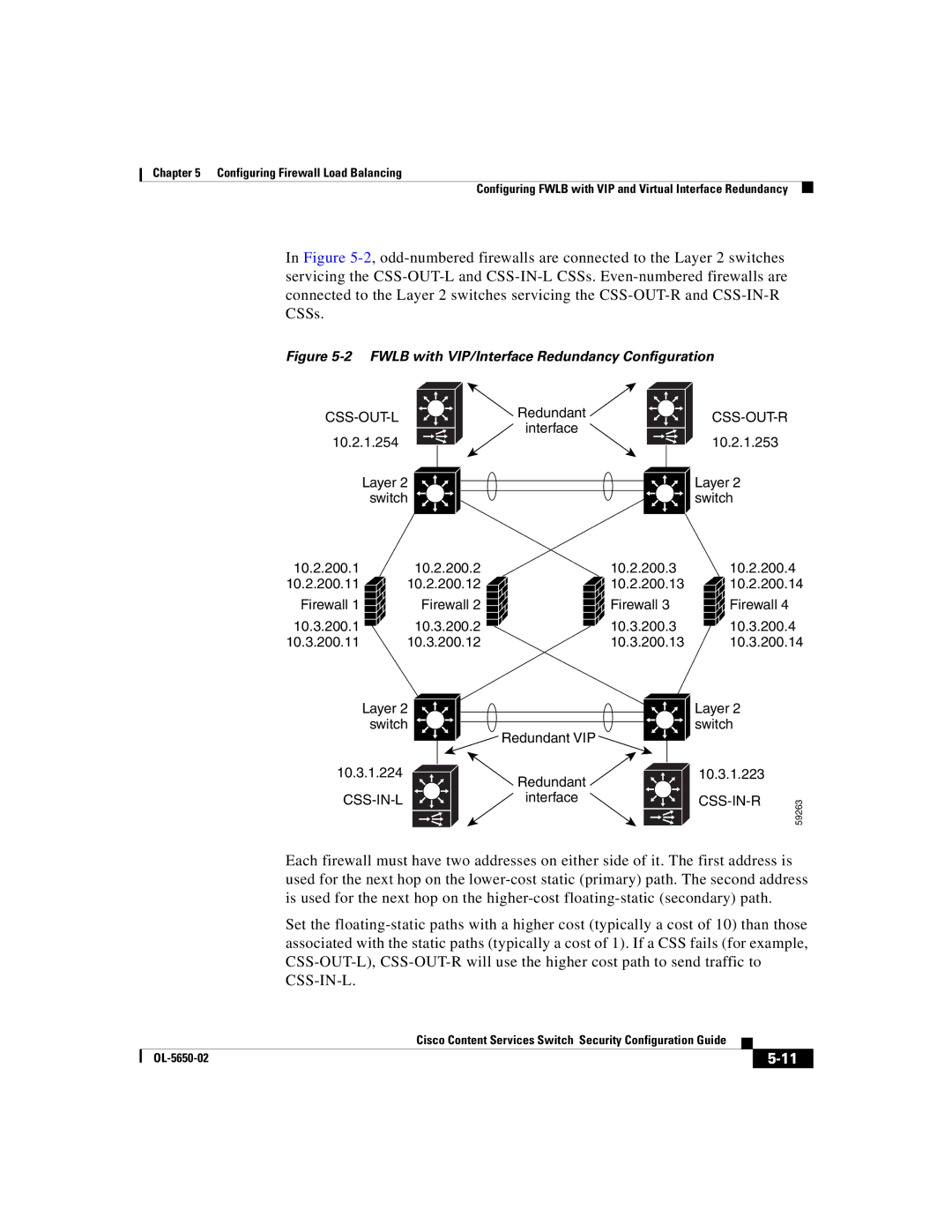
In Figure
Figure 5-2 FWLB with VIP/Interface Redundancy Configuration
10.2.1.254
Layer 2 switch
![]() Redundant
Redundant ![]()
interface
CSS-OUT-R
10.2.1.253
Layer 2 switch
10.2.200.1 | 10.2.200.2 | 10.2.200.3 |
10.2.200.11 | 10.2.200.12 | 10.2.200.13 |
Firewall 1 | Firewall 2 | Firewall 3 |
10.3.200.1 | 10.3.200.2 | 10.3.200.3 |
10.3.200.11 | 10.3.200.12 | 10.3.200.13 |
10.2.200.4 ![]() 10.2.200.14
10.2.200.14
![]()
![]()
![]() Firewall 4
Firewall 4
10.3.200.4
10.3.200.14
Layer 2 switch
10.3.1.224
![]() Redundant VIP
Redundant VIP ![]()
![]() Redundant
Redundant ![]()
interface
Layer 2 switch
10.3.1.223 |
|
59263 | |
|
Each firewall must have two addresses on either side of it. The first address is used for the next hop on the
Set the
|
| Cisco Content Services Switch Security Configuration Guide |
|
|
|
|
| ||
|
|
|
| |
|
|
|