Installing a Port Adapter
Caution To prevent jamming the carrier between the upper and the lower edges of the port adapter slot and to ensure that the edge connector at the rear of the port adapter mates with the connector at the rear of the port adapter slot, make certain that the leading edges of the carrier are between the upper and the lower slot edges, as shown in the cutaway in Figure
Caution To ensure a positive ground attachment between the port adapter carrier and the VIP2 motherboard and port adapter slot, and to ensure that the connectors at the rear of the port adapter and slot mate properly, position the carrier between the upper and the lower slot edges, as shown in Figure
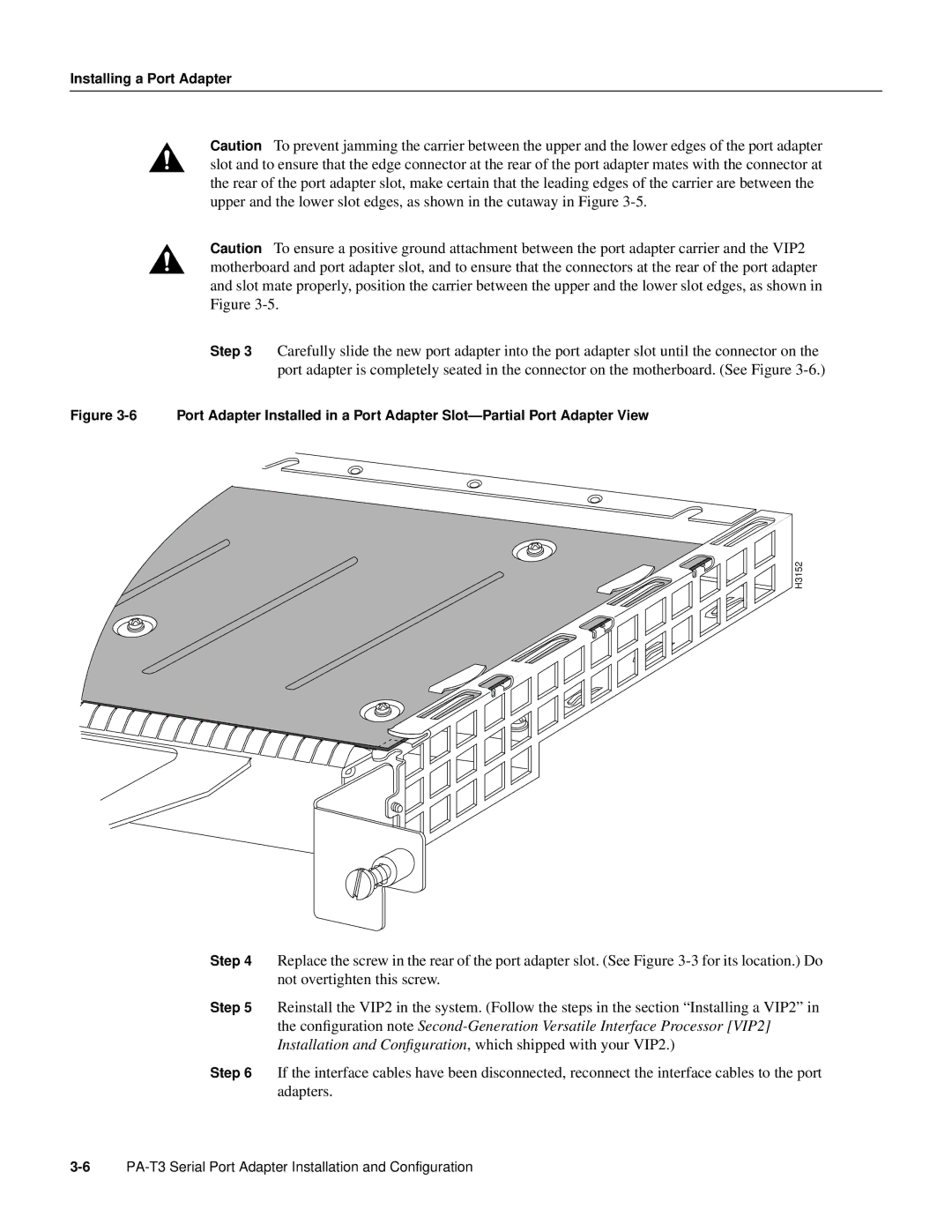
Step 3 Carefully slide the new port adapter into the port adapter slot until the connector on the port adapter is completely seated in the connector on the motherboard. (See Figure
Figure 3-6 Port Adapter Installed in a Port Adapter Slot—Partial Port Adapter View
H3152
Step 4 Replace the screw in the rear of the port adapter slot. (See Figure
Step 5 Reinstall the VIP2 in the system. (Follow the steps in the section “Installing a VIP2” in the configuration note
Step 6 If the interface cables have been disconnected, reconnect the interface cables to the port adapters.