Chapter 3 Maintaining the Server
Installing or Replacing Server Components
Replacing Fan Modules
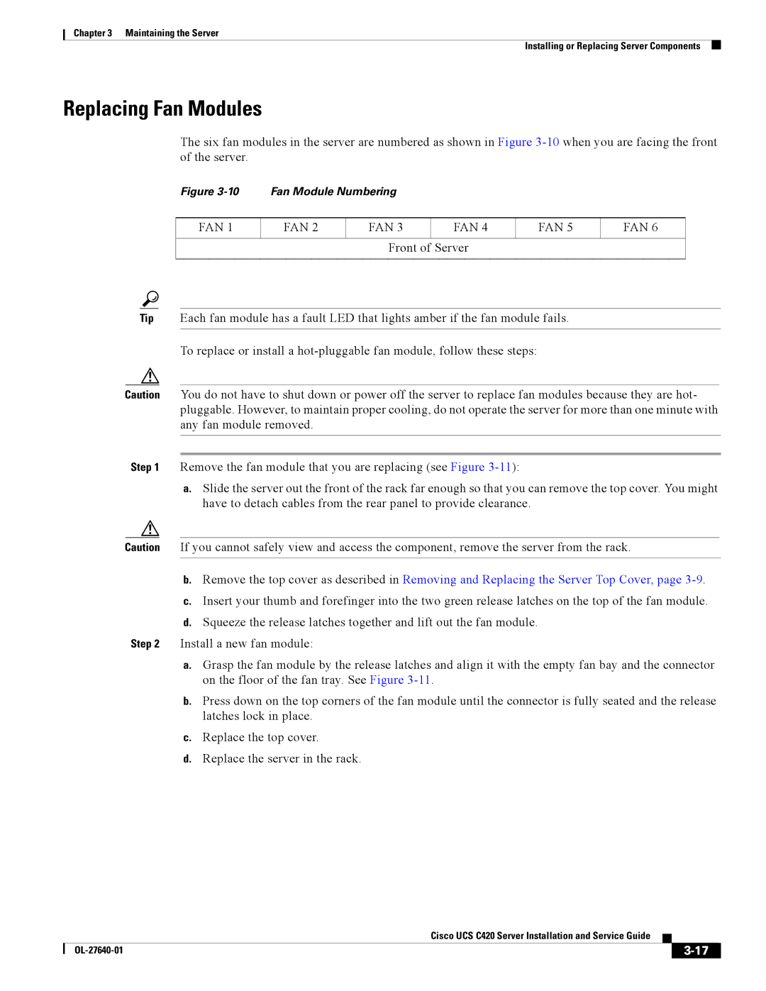
The six fan modules in the server are numbered as shown in Figure
Figure 3-10 Fan Module Numbering
FAN 1
FAN 2
FAN 3
FAN 4
FAN 5
FAN 6
Front of Server
Tip Each fan module has a fault LED that lights amber if the fan module fails.
To replace or install a
Caution You do not have to shut down or power off the server to replace fan modules because they are hot- pluggable. However, to maintain proper cooling, do not operate the server for more than one minute with any fan module removed.
Step 1 Remove the fan module that you are replacing (see Figure
a.Slide the server out the front of the rack far enough so that you can remove the top cover. You might have to detach cables from the rear panel to provide clearance.
Caution If you cannot safely view and access the component, remove the server from the rack.
b.Remove the top cover as described in Removing and Replacing the Server Top Cover, page
c.Insert your thumb and forefinger into the two green release latches on the top of the fan module.
d.Squeeze the release latches together and lift out the fan module.
Step 2 Install a new fan module:
a.Grasp the fan module by the release latches and align it with the empty fan bay and the connector on the floor of the fan tray. See Figure
b.Press down on the top corners of the fan module until the connector is fully seated and the release latches lock in place.
c.Replace the top cover.
d.Replace the server in the rack.
|
| Cisco UCS C420 Server Installation and Service Guide |
|
| |
|
|
| |||
|
|
|
|
| |
|
|
|
| ||