Chapter 3 Maintaining the Server
|
|
|
|
| Installing or Replacing Server Components |
| |
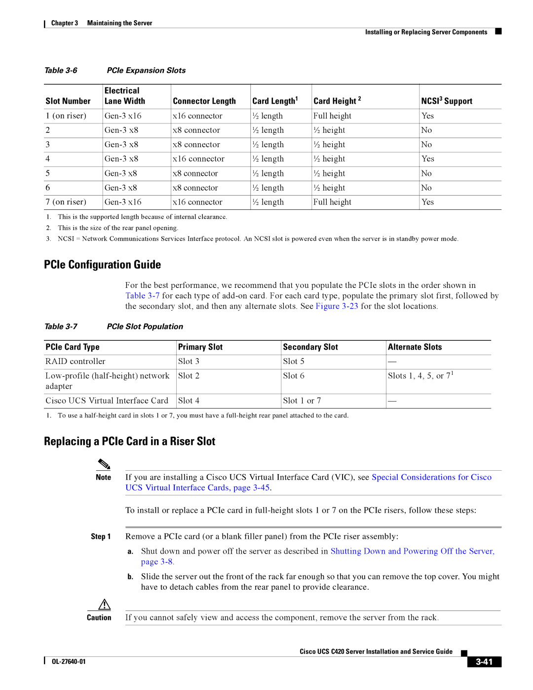
Table | PCIe Expansion Slots |
|
|
|
|
| |
|
|
|
|
|
|
|
|
| Electrical |
| Card Length1 | Card Height 2 |
| NCSI3 Support | |
Slot Number | Lane Width | Connector Length |
| ||||
1 (on riser) | x16 connector | ½ length | Full height |
| Yes | ||
|
|
|
|
|
|
|
|
2 | x8 connector | ½ length | ½ height |
| No | ||
|
|
|
|
|
|
|
|
3 | x8 connector | ½ length | ½ height |
| No | ||
|
|
|
|
|
|
|
|
4 | x16 connector | ½ length | ½ height |
| Yes | ||
|
|
|
|
|
|
|
|
5 | x8 connector | ½ length | ½ height |
| No | ||
|
|
|
|
|
|
|
|
6 | x8 connector | ½ length | ½ height |
| No | ||
|
|
|
|
|
|
|
|
7 (on riser) | x16 connector | ½ length | Full height |
| Yes | ||
|
|
|
|
|
|
|
|
1.This is the supported length because of internal clearance.
2.This is the size of the rear panel opening.
3.NCSI = Network Communications Services Interface protocol. An NCSI slot is powered even when the server is in standby power mode.
PCIe Configuration Guide
For the best performance, we recommend that you populate the PCIe slots in the order shown in Table
Table | PCIe Slot Population |
|
| |
|
|
|
|
|
PCIe Card Type |
| Primary Slot | Secondary Slot | Alternate Slots |
|
|
|
|
|
RAID controller |
| Slot 3 | Slot 5 | — |
|
|
|
| |
Slot 2 | Slot 6 | Slots 1, 4, 5, or 71 | ||
adapter |
|
|
|
|
|
|
|
| |
Cisco UCS Virtual Interface Card | Slot 4 | Slot 1 or 7 | — | |
|
|
|
|
|
1. To use a
Replacing a PCIe Card in a Riser Slot
Note If you are installing a Cisco UCS Virtual Interface Card (VIC), see Special Considerations for Cisco UCS Virtual Interface Cards, page
To install or replace a PCIe card in
Step 1 Remove a PCIe card (or a blank filler panel) from the PCIe riser assembly:
a.Shut down and power off the server as described in Shutting Down and Powering Off the Server, page
b.Slide the server out the front of the rack far enough so that you can remove the top cover. You might have to detach cables from the rear panel to provide clearance.
Caution If you cannot safely view and access the component, remove the server from the rack.
|
| Cisco UCS C420 Server Installation and Service Guide |
|
| |
|
|
| |||
|
|
|
|
| |
|
|
|
| ||
