Chapter 3 Maintaining the Server
Installing or Replacing Server Components
DIMM Population Rules
Observe the following guidelines when installing or replacing DIMMs (see Figure
•The minimum configuration is one DIMM installed in any of CPU1’s blue sockets (A1, B1, C1, D1).
•When populating a channel, fill the blue socket first, and then fill the black sockets (1, 2, 3).
•The server supports one, two, or three DIMMs per channel for single- or
•The server supports only one or two
•The server supports RDIMMs or LRDIMMs. Do not mix RDIMMs and LRDIMMs in a server.
•Unregistered DIMMs (UDIMMs) and
•For memory mirroring population rules, see Memory Mirroring Mode, page
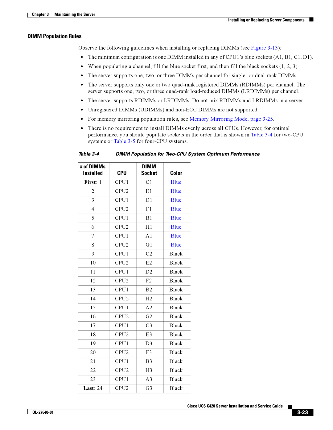
•There is no requirement to install DIMMs evenly across all CPUs. However, for optimal performance, you should populate sockets in the order that is shown in Table
|
| Table | DIMM Population for | ||||||
|
|
|
|
|
|
|
|
|
|
|
| # of DIMMs |
| DIMM |
|
|
|
|
|
|
| Installed | CPU | Socket | Color | ||||
|
|
|
|
|
|
| |||
|
| First: 1 | CPU1 | C1 | Blue | ||||
|
|
|
|
|
| ||||
2 | CPU2 | E1 | Blue | ||||||
|
|
|
|
|
| ||||
3 | CPU1 | D1 | Blue | ||||||
|
|
|
|
|
| ||||
4 | CPU2 | F1 | Blue | ||||||
|
|
|
|
|
| ||||
5 | CPU1 | B1 | Blue | ||||||
|
|
|
|
|
| ||||
6 | CPU2 | H1 | Blue | ||||||
|
|
|
|
|
| ||||
7 | CPU1 | A1 | Blue | ||||||
|
|
|
|
|
| ||||
8 | CPU2 | G1 | Blue | ||||||
|
|
|
|
|
| ||||
9 | CPU1 | C2 | Black | ||||||
|
|
|
|
|
| ||||
10 | CPU2 | E2 | Black | ||||||
|
|
|
|
|
| ||||
11 | CPU1 | D2 | Black | ||||||
|
|
|
|
|
| ||||
12 | CPU2 | F2 | Black | ||||||
|
|
|
|
|
| ||||
13 | CPU1 | B2 | Black | ||||||
|
|
|
|
|
| ||||
14 | CPU2 | H2 | Black | ||||||
|
|
|
|
|
| ||||
15 | CPU1 | A2 | Black | ||||||
|
|
|
|
|
| ||||
16 | CPU2 | G2 | Black | ||||||
|
|
|
|
|
| ||||
17 | CPU1 | C3 | Black | ||||||
|
|
|
|
|
| ||||
18 | CPU2 | E3 | Black | ||||||
|
|
|
|
|
| ||||
19 | CPU1 | D3 | Black | ||||||
|
|
|
|
|
| ||||
20 | CPU2 | F3 | Black | ||||||
|
|
|
|
|
| ||||
21 | CPU1 | B3 | Black | ||||||
|
|
|
|
|
| ||||
22 | CPU2 | H3 | Black | ||||||
|
|
|
|
|
| ||||
23 | CPU1 | A3 | Black | ||||||
|
|
|
|
|
|
| |||
|
| Last: 24 | CPU2 | G3 | Black | ||||
|
|
|
|
|
|
|
|
| |
|
|
|
|
| Cisco UCS C420 Server Installation and Service Guide |
|
| ||
|
|
|
|
|
| ||||
|
|
|
|
|
|
|
|
|
|
|
|
|
|
|
|
|
| ||
|
|
|
|
|
|
| |||