CBM-270 User’s Manual
7.SERIAL INTERFACE
7.1Specifications
(1) | Synchronous system | : Asynchronous |
(2) | Baud rate | : 1,200, 2,400, 4,800, 9,600, 19,200 bps (Selected by the user) |
(3) |
| |
| Start bits | : 1 bit |
| Data bits | : 8 bits or 7 bits (Setting upon shipment) |
| Parity bits | : Odd, even, or no parity (Selected by the user) |
| Stop bits | : 1 bit or more |
(4)Signal polarity
| ∙Mark | = | Logic "1" | ||
| ∙Space | = | Logic "0" (+3 ∼ +12 V) | ||
(5) | Received data (RXD signal) |
|
| ||
| ∙Mark | = | 1 |
|
|
| ∙Space | = | 0 |
|
|
(6) | Reception control (DTR signal) |
| |||
| ∙Mark | : | Data not transferable | ||
| ∙Space | : | Data transferable | ||
(7) | Transmission control (TXD signal) | ||||
| ∙DC1 code(11H) | : | Data receivable | ||
| ∙DC3 code(13H) | : | Data not receivable | ||
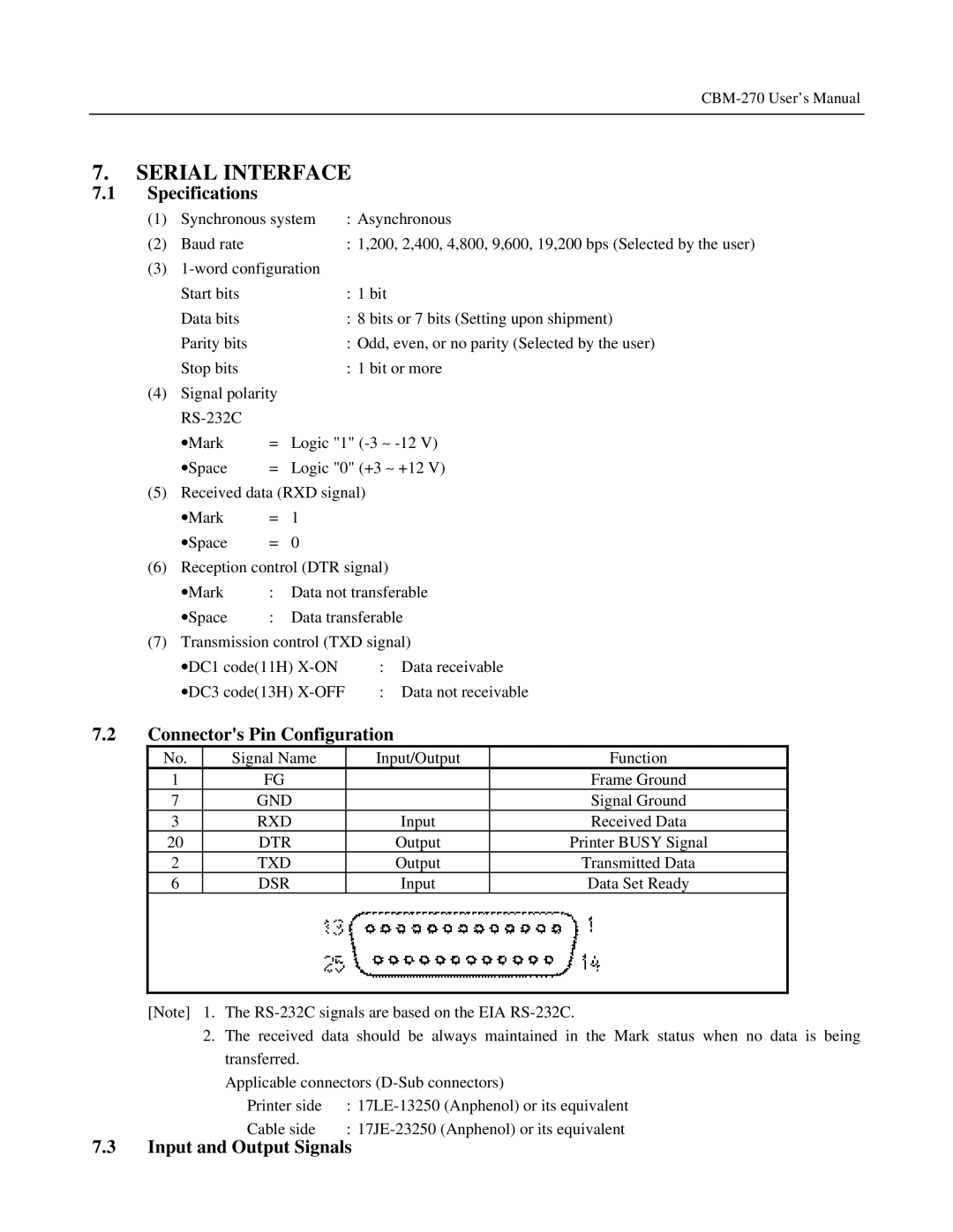
7.2Connector's Pin Configuration
No. | Signal Name | Input/Output | Function |
1 | FG |
| Frame Ground |
7 | GND |
| Signal Ground |
3 | RXD | Input | Received Data |
20 | DTR | Output | Printer BUSY Signal |
2 | TXD | Output | Transmitted Data |
6 | DSR | Input | Data Set Ready |
|
|
|
|
[Note] 1. The
2.The received data should be always maintained in the Mark status when no data is being transferred.
Applicable connectors
Printer side | : | |
Cable side | : |