CBM-270 User’s Manual
(2)Data bits + Parity bit
The system samples the data bits and parity bit for the 1 bit worth of time from 1/2 start bit and assumes the then status as the data for the relevant bits. The bits are called Bit 0, Bit 1, ..., Parity bit, counting from the one closest to the start bit.
(3)Stop bit
The stop bit is the Mark level of 1 bit or more. If a space is detected in detecting the stop bit, a framing error will result.
7.3.3Error Detection
The system detects a parity, framing, or overrun error. If an error is detected, the relevant data will be stored in the buffer as "?".
(1)Parity error
With a parity check specified, if an error is detected at parity check time, the relevant data will be stored in the buffer as "?".
(2)Framing error
This error results if the Space status is detected at stop bit detection time. The relevant data will be stored in the buffer as "?".
(3)Overrun error
If an overrun error is detected, the relevant data will be stored in the buffer as "?".
7.3.4Data Receiving Control
If DTR/DSR control has been selected, the data from the host side will be received when the BUSY signal is at "Low," but not received when at "High." If DTR/DSR has not been selected, the data from the host side will be received after sending XON, but not after sending XOFF.
7.3.5Buffering
To transfer the data to the input buffer, there are two control signals available: DTR signal and TXD signal. The host side is immediately freed, since the data can be buffered up to 2 KB.
(1)DTR signal (See
(2)TXD signal (See
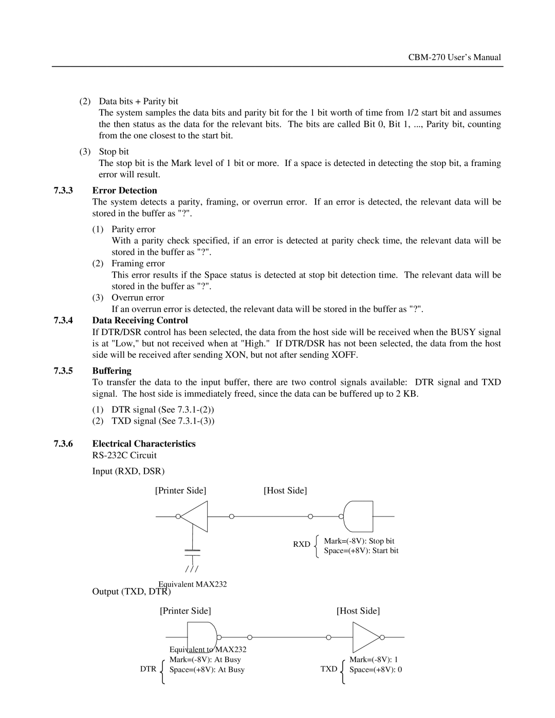
7.3.6Electrical Characteristics
Input (RXD, DSR)
[Printer Side] |
|
| [Host Side] | ||
|
|
|
|
|
|
|
|
|
|
|
|
|
|
|
|
|
|
|
|
|
|
|
|
RXD
Space=(+8V): Start bit
Equivalent MAX232
Output (TXD, DTR)
[Printer Side] | [Host Side] |
DTR
Equivalent to MAX232 |
|
| |
Space=(+8V): At Busy | TXD |
Space=(+8V): 0