CBM-270 User’s Manual
3.OUTER APPEARANCE AND COMPONENT PARTS
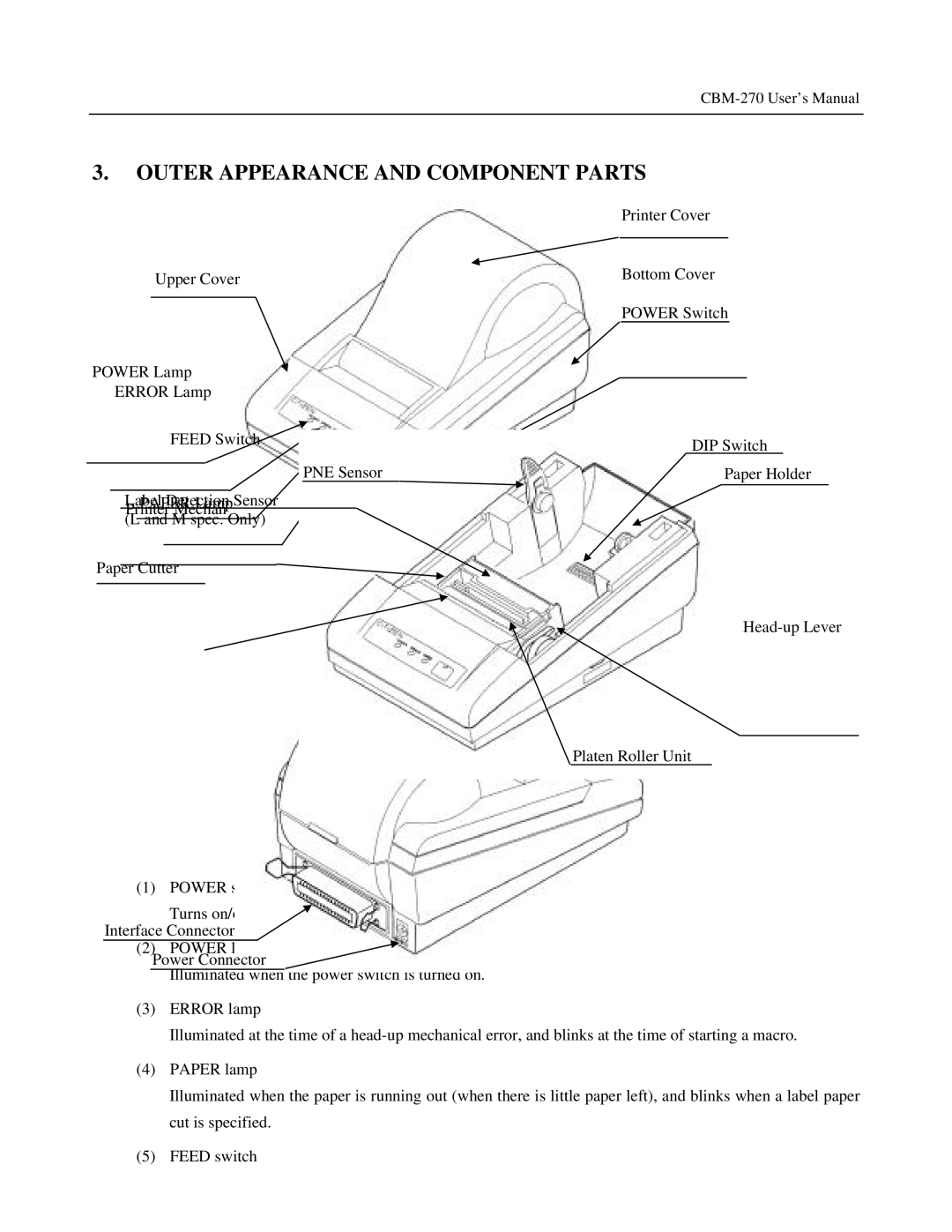
Upper Cover
POWER Lamp
ERROR Lamp
FEED Switch
PNE Sensor
LabelPAPERDetectionLampSensor Printer Mechanism
(L and M spec. Only)
Paper Cutter
(1) POWER switch
Turns on/off the power for the printer body. Interface Connector
(2) POWER lamp Power Connector
Illuminated when the power switch is turned on.
Printer Cover
Bottom Cover
POWER Switch
DIP Switch
Paper Holder
Platen Roller Unit
(3)ERROR lamp
Illuminated at the time of a
(4)PAPER lamp
Illuminated when the paper is running out (when there is little paper left), and blinks when a label paper cut is specified.
(5)FEED switch