iDP3550/3551 User ’s Manual
12. WINDER CONNECTOR
12.1Specifications of Winder Connector
(1)Winder drive signal
The winder drive signal is output synchronous with the LF signal.
(2)Electrical characteristics
1)Drive voltage: 24 V DC
2)Drive current: 0.8 A at maximum
12.2Connector's Pin Configuration
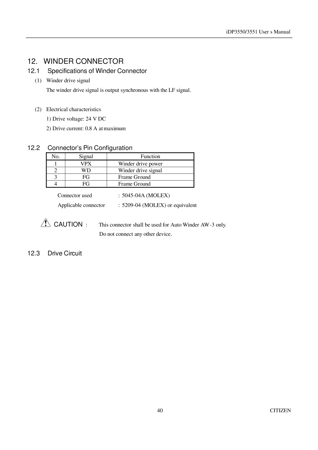
No. | Signal | Function |
|
1 | VPX | Winder drive power |
|
2 | WD | Winder drive signal |
|
3 | FG | Frame Ground |
|
4 | FG | Frame Ground |
|
Connector used | : | ||
Applicable connector | : | ||
CAUTION : • This connector shall be used for Auto Winder
Do not connect any other device.
12.3Drive Circuit
40 | CITIZEN |
