iDP3550/3551 User ’s Manual
9.3Input and Output Signals
9.3.1Input and Output Signals
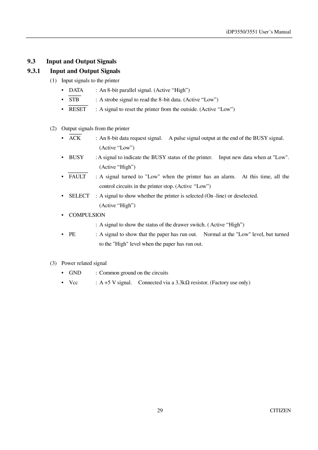
(1)Input signals to the printer
• | DATA | : An | |||||
|
|
|
|
|
|
|
|
• | STB | : A strobe signal to read the | |||||
|
|
|
| ||||
• | RESET | : A signal to reset the printer from the outside. (Active “Low”) | |||||
(2) Output signals from the printer | |||||||
|
|
|
|
|
|
| |
• | ACK | : An | |||||
|
|
|
|
|
|
| (Active “Low”) |
• | BUSY | : A signal to indicate the BUSY status of the printer. Input new data when at "Low". | |||||
|
|
|
|
|
|
| (Active “High”) |
|
|
|
|
| |||
• | FAULT | : A signal turned to "Low" when the printer has an alarm. At this time, all the | |||||
|
|
|
|
|
|
| control circuits in the printer stop. (Active “Low”) |
• | SELECT | : A signal to show whether the printer is selected (On | |||||
|
|
|
|
|
|
| (Active “High”) |
•COMPULSION
:A signal to show the status of the drawer switch. ( Active “High”)
• | PE | : A signal to show that the paper has run out. Normal at the "Low" level, but turned |
|
| to the "High" level when the paper has run out. |
(3) Power related signal | ||
• | GND | : Common ground on the circuits |
• | Vcc | : A +5 V signal. Connected via a 3.3k Ω resistor. (Factory use only) |
29 | CITIZEN |
