MOTOR CONNECTIONS
WARNING: FOR YOUR OWN SAFETY, TURN SWITCH "OFF" AND REMOVE PLUG FROM POWER SOURCE
OUTLET BEFORE PROCEEDING.
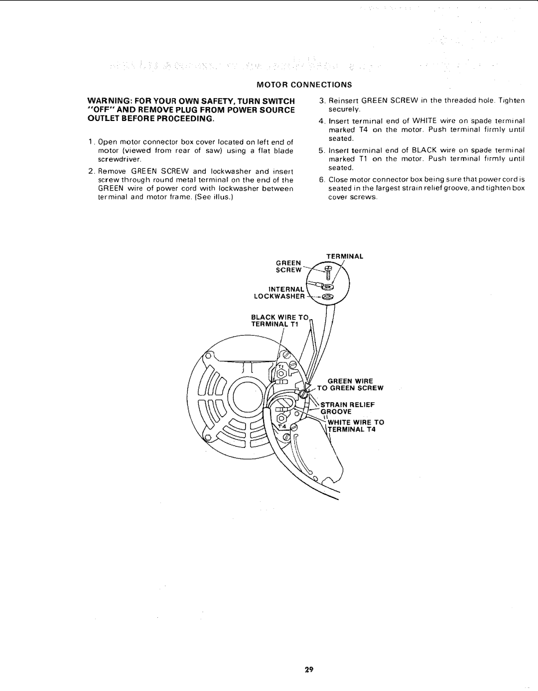
1.Open motor connector box cover located on left end of motor (viewed from rear of saw) using a flat blade screwdriver.
2.Remove GREEN SCREW and Iockwasher and insert
screw through round metal terminal on the end of the
GREEN wire of power cord with Iockwasher between terminal and motor frame. (See illus.)
3.Reinsert GREEN SCREW in the threadedhote Tighten securely.
4, Insert terminal end of WHITE wire on spade terminal
marked T4 on the motor Push terminal firmly until seated.
5.Insert terminal end of BLACK wire on spade terminal marked T1 on the motor. Push terminal firmly until seated.
6 Close motor connector box being sure that power cord is seated in the largest strain relief groove, and tighten box cover screws
TERMINAL
GREEN
INTERNAL t
LOCKWASHER
BLACK WIRE TO
TERMINAL T1
GREEN WIRE _TO GREEN SCREW
;TRAIN RELIEF
29