Save This Manual For Future Reference
Two Table Extensions
Rip Fence Miter Gauge
Sears, Roebuck and Co., Hoffman Estates, IL US,A
Sears, Roebuck and Co, D/817 WA Hoffman Estates, IL
Safety Instructions For Table Saw
Safety Signal Words Before Using The Saw
When Installing Or Moving The Saw
Before Each Use
Whenever Sawblade Is Spinning
Safety Instructions For Table Saws
Dress for safety
Plan Ahead To Protect Your Eyes, Hands, Face and Ears
Featherboard
Additional Safety Instructions
While Thru-sawing
Grain
Glossary of Terms for Woodworking
Miter Cut
Molding
Make sure this
Motor Specifications
110-120Volt, 60 Hz. Tool Information
Properly Prong Plug Grounded Prong Outlet
Requirements
Motor Specifications and Electrical
Wire Sizes
Extension Wire Sizes Required Cord Length For A.W.G
Contents
Unpacking and Checking Contents
Loose Parts
List
Loose
Parts
Assembling Steel Legs
Installing Handwheels and Bevel Pointer
Mounting Your Saw
Leg Set Flat Washer
Bench Mounting
Assembling Table Extensions
Assembly
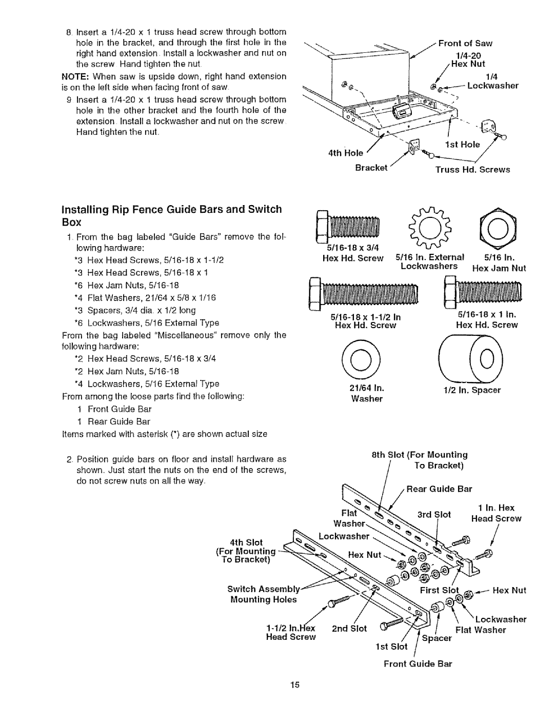
Installing Rip Fence Guide Bars and Switch
Lockwas her
Hex Nuts Lockwashers
Extension
Wire Tie
Aligning Extensions
Could be hit or cut
Leveling Tab Edge
Checking Table Insert
Installing Blade Guard
Port AndBracket To
Exacti-Cut Table Insert Tilt Handwheel Elevation Handwheel
On-Off Switch
Getting to Know Your Table Saw
Rip Fence
Lock Knob
Push To Tighen
Removing and Installing Sawblade
Inspect Your Blade
Safety Instructions for Basic Saw Operations
Before Each Use
Inspect your saw
Planyour cut
Avoid Accidental Starting
Dont Force Tool
Work Feed Devices
Push Stick
Push Block
Thick Side Plywood Finished Auxiliary Fence
Auxiliary Fence
Making the handle
3E-l!2rL Thick Plywood Base
Crosscutting
Using the Miter Gauge
Additional Safety Instructions for Crosscutting
Basic Saw Operations
Crosscutting
Miter Crosscutting
Bevel Crosscutting
Compound Crosscutting
Always Support Long Or Wide Workpieces
Using the Rip Fence
Additional Safety instructions for Rip Cuts
Ripping
Push Block
Featherhoar Facing
Using Featherboards for Thru-Sawing
Bevel Ripping Narrow Work
Work
Ond pass
Using Featherboards for Non Thru-Sawing
Resawing
Work Sup
Making
LcelSaeJ
Arbor
Fence
Molding Cutting
Adjustments
Mended accessories
Ploughing and Molding
Rip Fence
Self Aligning Spring Adjustment
Lock Handle
Rip Fence Alignment Adjustment
Adjusting Rip Scale Indicator
Slide Spring To Adjust Pressure
Wrench
To check for parallelism
3t16
Locking screws
Blade Tilt, or Squareness of Blade to Table
Pointer Adjusting Screw
With Piece
Screws
Blade Elevation
Tilt and Elevation Mechanism
Tilt Screw
Maintaining Your Table Saw
Maintenance
Pivot Nut
Lubrication
Remedy
Sears Recommends the Following Accessories
Into blade
Probable Cause
Parts List for Craftsman 10 Inch Fable Saw Model No
Repair Parts
201
Parts List for Craftsman 10 Inch Table Saw Model No
Description
Parts List for Craftsman 10 Inch Table Saw Model No. t
201!17
Parts list for Craftsman 10 Inch Table Saw
Key Pad No Description
Parts List for Craftsman 10 Inch Table Saw Model
Repair Parts
Model
Parts List for Craftsman 10 Inch Table Saw
Model No
Rear Guide Bar Ref
Key
Foot Leveling
Key j
Co., Hoffman Estates, IL U.S.A
For the repair or replacement paris you need
For in-home major brand repair service
Sears, Roebuck