Installing the VoIP V3 Indoor Intercom 12
Intercom Connections
2.3 Intercom Setup
2.3.1 Intercom Connections
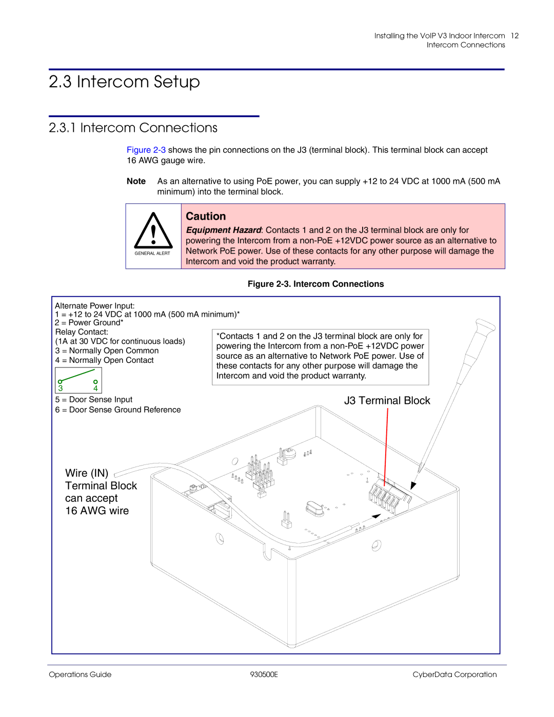
Figure 2-3 shows the pin connections on the J3 (terminal block). This terminal block can accept 16 AWG gauge wire.
Note As an alternative to using PoE power, you can supply +12 to 24 VDC at 1000 mA (500 mA minimum) into the terminal block.
GENERAL ALERT
Caution
Equipment Hazard: Contacts 1 and 2 on the J3 terminal block are only for powering the Intercom from a
Figure 2-3. Intercom Connections
Alternate Power Input:
1 = +12 to 24 VDC at 1000 mA (500 mA minimum)* 2 = Power Ground*
Relay Contact:
(1A at 30 VDC for continuous loads)
3 = Normally Open Common
4 = Normally Open Contact
3 | 4 |
*Contacts 1 and 2 on the J3 terminal block are only for powering the Intercom from a
5 | = Door Sense Input | J3 Terminal Block | ||
6 | = Door Sense Ground Reference |
|
|
|
|
| |||
|
|
|
|
|
|
|
|
|
|
Wire (IN)  Terminal Block can accept
16 AWG wire
Operations Guide | 930500E | CyberData Corporation |