Installing the VoIP V3 Indoor Intercom 16
Identifying the VoIP Intercom Connectors
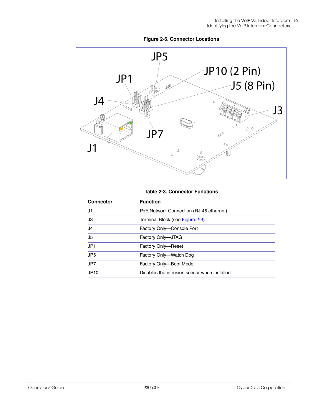
Figure 2-6. Connector Locations
| JP5 | |
JP1 | JP10 (2 Pin) | |
J5 (8 Pin) | ||
| ||
J4 | J3 | |
| ||
J1 | JP7 | |
|
| Table |
|
|
Connector | Function |
|
|
J1 | PoE Network Connection |
|
|
J3 | Terminal Block (see Figure |
|
|
J4 | Factory |
|
|
J5 | Factory |
|
|
JP1 | Factory |
|
|
JP5 | Factory |
|
|
JP7 | Factory |
|
|
JP10 | Disables the intrusion sensor when installed. |
|
|
Operations Guide | 930500E | CyberData Corporation |