CY8C20x36/46/66, CY8C20396
PSoC® Functional Overview
The PSoC family consists of
The architecture for this device family, as shown in the Block Diagram on page 2, is comprised of three main areas: the Core, the CapSense Analog System, and the System Resources (including a full speed USB port). A common, versatile bus allows connection between IO and the analog system. Each CY8C20x36/46/66, CY8C20396 PSoC device includes a dedicated CapSense block that provides sensing and scanning control circuitry for capacitive sensing applications. Depending on the PSoC package, up to 36 general purpose IO (GPIO) are also included. The GPIO provides access to the MCU and analog mux.
PSoC Core
The PSoC Core is a powerful engine that supports a rich instruction set. It encompasses SRAM for data storage, an interrupt controller, sleep and watchdog timers, and IMO (internal main oscillator) and ILO (internal low speed oscillator). The CPU core, called the M8C, is a powerful processor with speeds up to 24 MHz. The M8C is a
System Resources provide additional capability, such as configurable USB and I2C slave/SPI
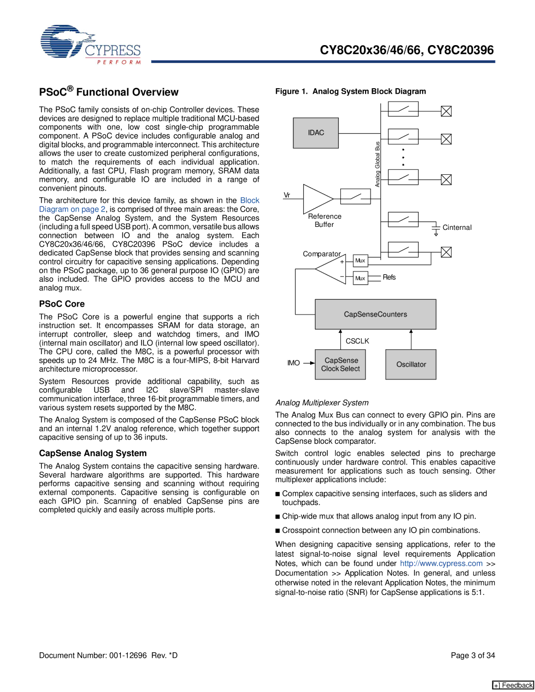
The Analog System is composed of the CapSense PSoC block and an internal 1.2V analog reference, which together support capacitive sensing of up to 36 inputs.
CapSense Analog System
The Analog System contains the capacitive sensing hardware. Several hardware algorithms are supported. This hardware performs capacitive sensing and scanning without requiring external components. Capacitive sensing is configurable on each GPIO pin. Scanning of enabled CapSense pins are completed quickly and easily across multiple ports.
Figure 1. Analog System Block Diagram
IDAC |
|
| Analog Global Bus |
Vr |
|
Reference |
|
Buffer | Cinternal |
| |
Comparator |
|
Mux |
|
Mux | Refs |
|
|
|
|
| CapSenseCounters | |||
|
|
|
|
| ||||
|
|
|
|
|
|
|
|
|
|
|
|
|
| CSCLK |
|
| |
|
|
|
|
|
|
| ||
|
|
|
|
|
|
|
|
|
IMO |
|
| CapSense |
| Oscillator | |||
|
| Clock Select |
| |||||
|
|
|
|
|
|
| ||
|
|
|
|
|
|
|
|
|
Analog Multiplexer System
The Analog Mux Bus can connect to every GPIO pin. Pins are connected to the bus individually or in any combination. The bus also connects to the analog system for analysis with the CapSense block comparator.
Switch control logic enables selected pins to precharge continuously under hardware control. This enables capacitive measurement for applications such as touch sensing. Other multiplexer applications include:
■Complex capacitive sensing interfaces, such as sliders and touchpads.
■
■Crosspoint connection between any IO pin combinations.
When designing capacitive sensing applications, refer to the latest
Document Number: | Page 3 of 34 |
[+] Feedback
