CYDC256B16, CYDC128B16,
CYDC064B16, CYDC128B08,
CYDC064B08
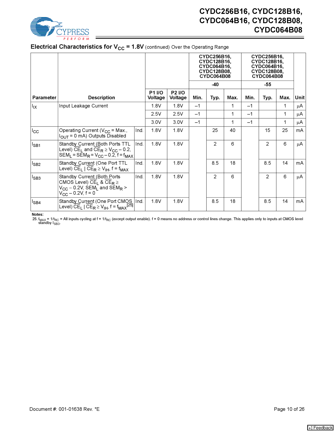
Electrical Characteristics for VCC = 1.8V (continued) Over the Operating Range
|
|
|
|
| CYDC256B16, | CYDC256B16, |
| ||||
|
|
|
|
| CYDC128B16, | CYDC128B16, |
| ||||
|
|
|
|
| CYDC064B16, | CYDC064B16, |
| ||||
|
|
|
|
| CYDC128B08, | CYDC128B08, |
| ||||
|
|
|
|
| CYDC064B08 | CYDC064B08 |
| ||||
|
|
|
|
|
|
|
| ||||
|
|
|
|
|
|
|
|
|
|
|
|
Parameter | Description |
| P1 I/O | P2 I/O | Min. | Typ. | Max. | Min. | Typ. | Max. | Unit |
| Voltage | Voltage | |||||||||
IIX | Input Leakage Current |
| 1.8V | 1.8V |
| 1 |
| 1 | µA | ||
|
|
| 2.5V | 2.5V |
| 1 |
| 1 | µA | ||
|
|
|
|
|
|
|
|
|
|
|
|
|
|
| 3.0V | 3.0V |
| 1 |
| 1 | µA | ||
|
|
|
|
|
|
|
|
|
|
|
|
ICC | Operating Current (VCC = Max., | Ind. | 1.8V | 1.8V |
| 25 | 40 |
| 15 | 25 | mA |
| IOUT = 0 mA) Outputs Disabled |
|
|
|
|
|
|
|
|
|
|
ISB1 | Standby Current (Both Ports TTL | Ind. | 1.8V | 1.8V |
| 2 | 6 |
| 2 | 6 | µA |
| Level) CEL and CER ≥ VCC – 0.2, |
|
|
|
|
|
|
|
|
|
|
| SEML = SEMR = VCC – 0.2, f = fMAX |
|
|
|
|
|
|
|
|
|
|
ISB2 | Standby Current (One Port TTL | Ind. | 1.8V | 1.8V |
| 8.5 | 18 |
| 8.5 | 14 | mA |
| Level) CEL CER ≥ VIH, f = fMAX |
|
|
|
|
|
|
|
|
|
|
ISB3 | Standby Current (Both Ports | Ind. | 1.8V | 1.8V |
| 2 | 6 |
| 2 | 6 | µA |
| CMOS Level) CEL & CER ≥ |
|
|
|
|
|
|
|
|
|
|
| VCC − 0.2V, SEML and SEMR > |
|
|
|
|
|
|
|
|
|
|
| VCC – 0.2V, f = 0 |
|
|
|
|
|
|
|
|
|
|
ISB4 | Standby Current (One Port CMOS | Ind. | 1.8V | 1.8V |
| 8.5 | 18 |
| 8.5 | 14 | mA |
| Level) CEL CER ≥ VIH, f = fMAX[25] |
|
|
|
|
|
|
|
|
|
|
Notes:
25.fMAX = 1/tRC = All inputs cycling at f = 1/tRC (except output enable). f = 0 means no address or control lines change. This applies only to inputs at CMOS level standby ISB3.
Document #: | Page 10 of 26 |
[+] Feedback