or an end node using a
Please refer to the following chart when deciding on the type of cable necessary for a given connection:
DEVICE | PORT | DEVICE BEING | PORT | CABLE TO USE |
| USED | CONNECTED | TYPE |
|
|
|
|
|
|
|
| Hub or | Normal | Crossover (X) |
|
| Switch |
|
|
| Normal | Uplink | ||
|
|
|
|
|
Router |
| Server (or PC) |
| |
|
|
|
|
|
|
| Hub or | Normal | |
|
| Switch |
|
|
| Uplink | Uplink | Crossover (X) | |
|
|
|
|
|
|
| Server (or PC) |
| Crossover (X) |
|
|
|
|
|
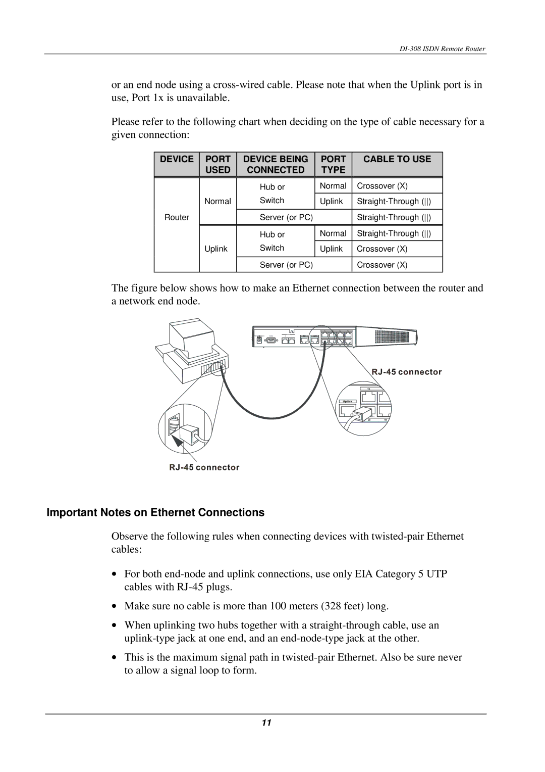
The figure below shows how to make an Ethernet connection between the router and a network end node.
Important Notes on Ethernet Connections
Observe the following rules when connecting devices with
•For both
•Make sure no cable is more than 100 meters (328 feet) long.
•When uplinking two hubs together with a
•This is the maximum signal path in
11