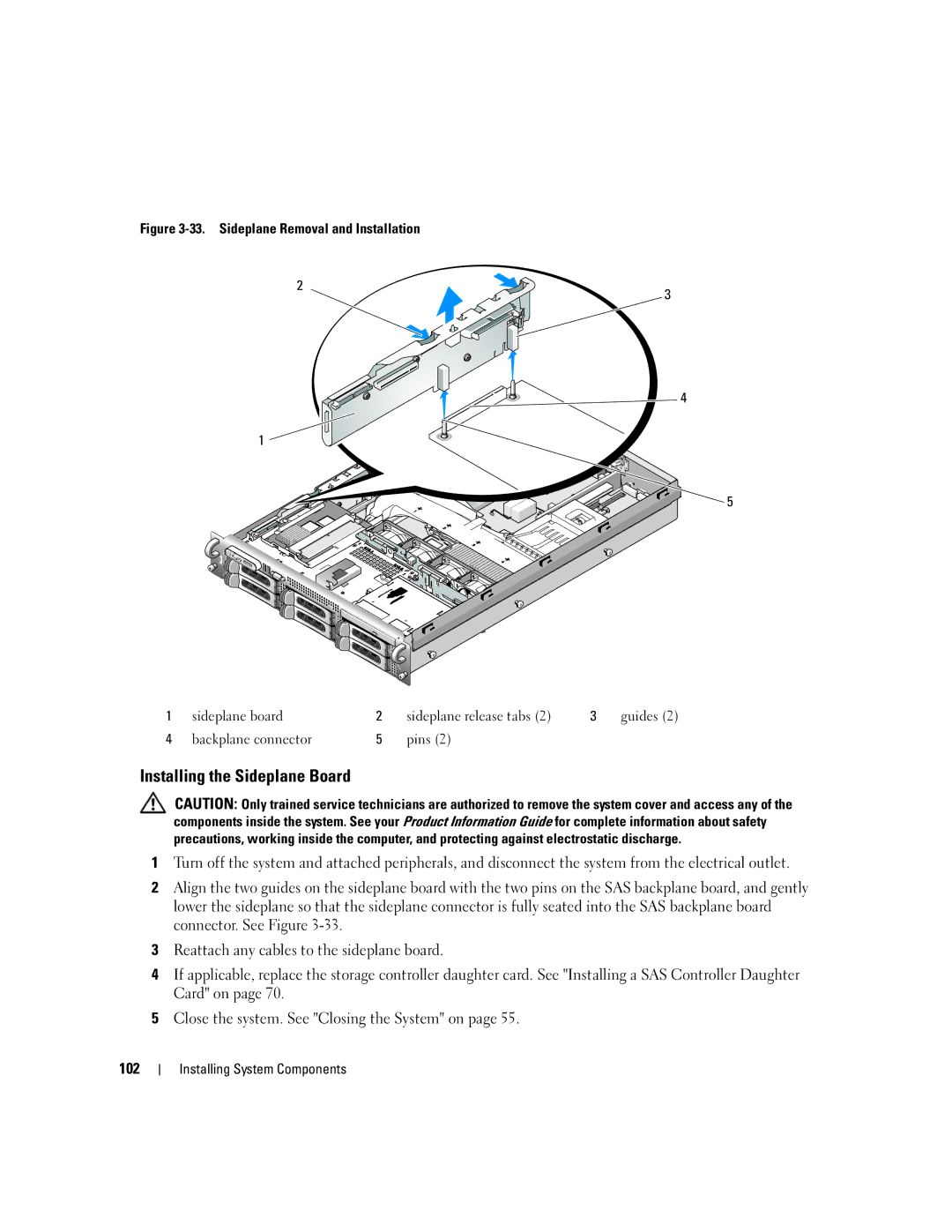
Figure 3-33. Sideplane Removal and Installation
2
3
![]() 4
4
1 ![]()
5
1 | sideplane board | 2 | sideplane release tabs (2) | 3 | guides (2) |
4 | backplane connector | 5 | pins (2) |
|
|
Installing the Sideplane Board
CAUTION: Only trained service technicians are authorized to remove the system cover and access any of the components inside the system. See your Product Information Guide for complete information about safety precautions, working inside the computer, and protecting against electrostatic discharge.
1Turn off the system and attached peripherals, and disconnect the system from the electrical outlet.
2Align the two guides on the sideplane board with the two pins on the SAS backplane board, and gently lower the sideplane so that the sideplane connector is fully seated into the SAS backplane board connector. See Figure
3Reattach any cables to the sideplane board.
4If applicable, replace the storage controller daughter card. See "Installing a SAS Controller Daughter Card" on page 70.
5Close the system. See "Closing the System" on page 55.
102